Download
1 / 27
290 likes | 356 Views
Explore forces of nature applied in mechanical & electrical engineering through water wheel and light bulb examples. Learn essential terminology, components like resistors, LEDs, and capacitors, practical circuits, and digital vs. analog circuits. Interactive exercises and simulations enhance understanding.

E N D
Electricity and Circuits Developed by Dr. Rhett Davis (NCSU) and Shodor
What Do Engineers Do? • Study the forces of nature • Apply them to do useful things • Example:Water Wheel • What are the forces? • How is it useful?
Water Wheels • Water-wheels are Mechanical Engineering • Today, we’ll look at Electrical Engineering = +
What do you need to make a Water Wheel Work? • Water – Makes everything work • River – Source of flowing water • Pipes – To direct the water where you want it to go and regulate the flow • Wheel – To convert the force of the flowing water into force to grind the wheat
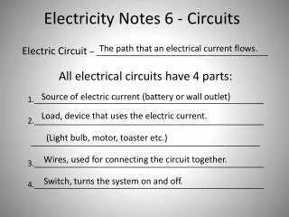
What’s a similar Electrical Engineering Problem? • Turn on a light • Water → Electricity • River→ Battery • Pipes → Resistors, Wires • Wheel → Light Bulb
What do you need to make a Light Bulb Work? • Electricity – Makes everything work • Battery – Source of flowing Electricity • Resistors, Wires – To direct the electricity where you want it to go and regulate the flow • Light Bulb – To convert the force of the flowing electricity into light
Terminology • Electric Potential – like the height of the water • Symbol (V) • Units (Volts - V) • Current – like the number of gallons of water that flow every second • Symbol (I) • Units (Amperes – A) • Power – like the amount of wheat that can be ground each second, or brightness of light • Symbol (P) • Units (Watts – W) • NOTE: P=I*V
Battery • Source of constant potential (9 V) • + lead (red wire) – outflow from high potential • - lead (black wire) – inflow to low potential
Light-Emitting Diode (LED) • Emits light when current flows through it • Current can only flow in one direction, from + to - (like a water wheel that won’t go in reverse) • Long lead (+) • Short lead (-)
Resistor • New term: • Resistance – how easy is it for current to flow • Symbol (R) • Unit (Ohm – Ω) • NOTE: V=I*R • New circuit element • Resistor • Regulates the flow of current • Like a pipe for electric current to flow • Resistance ~ 1/cross-section-area • A wire is like a resistor with a very low Resistance
Breadboards are used to connect things quickly You can proto-type circuits quickly Breadboard
Exercise • Use the battery, the breadboard, the resistor, and the LED to make the LED turn on. • Follow the “LED Circuit” in your handout. • Why is the resistor necessary?
Capacitor • Like a glass that holds water • Top of glass (+) long lead (no stripe), should always be at high potential • Bottom of glass (-) short lead (with stripe), should always be at low potential • The more electricity flows in, the higher the voltage (water level) • A large capacitor is like a wide glass • Needs more water (electricity) to get to the same height (voltage)
555 Timer Chip • Used to oscillate between a high (Vcc) and low (GND) voltages • Stays high until Threshold rises above 2/3 Vcc, then switches low and lets current flow in through Discharge pin • Stays low until Trigger falls below 1/3 Vcc, then switches high and stops letting current flow in through Discharge pin
Exercise • Go to http://falstad.com/circuit/ • Choose Circuits → 555 Timer Chip → Square Wave Generator • Build the circuit shown • Use the output to power the LED Circuit from first exercise • “555 Timer Circuit” in your handout gives the circuit, for convenience • Question: Which capacitor makes the LED blink faster? Why?
555 Timer Circuit • Tips: • Follow the rough layout shown here on your bread-board • Use the black wire and left rails for ground • Use the red wire and right rails for the 9V battery + lead
Digital Circuits • Analog Circuits • What we’ve seen up to now • can have any voltage (in our case, anything between 0V and 9V) • Useful for interfacing to the “real world” • Digital Circuits • can have only two voltages: high & low(in our case, only 0V and 5V) • Useful for processing information reliably
Transistors • Basically a switch • Two types that we will look at • NMOS – closed when input is high • PMOS – closed when input is low • Exercise • Go to http://falstad.com/circuit • Choose Circuits → Logic Families → CMOS → CMOS Inverter • Click to toggle input. What happens to the output?
Logic Gates • Can be used to build up complex functions • Exercise • Go to http://falstad.com/circuit • Choose Circuits → Logic Families → CMOS → CMOS NAND • Click to toggle inputs. What happens to the output?
Flip-Flops • Used to implement “memory” in a circuit • Allows behavior to change over time • Exercise • Go to http://falstad.com/circuit • Choose Circuits → Sequential Logic → Flip-Flops → Master-Slave Flip-Flop • Click to toggle input “D”. When does the output “Q” change?
Counters • Counts up from zero to a certain number and starts over • Binary arithmetic is used • An example of a more complex digital circuit • Exercise • Go to http://falstad.com/circuit • Choose Circuits → Sequential Logic → Counters → 4-bit Ripple Counter • Watch the output change. What is the highest count value? • What is the input “CLK”? What does it remind you of?
7493 Counter Chip • Combines all that we have discussed into one easy-to-use package • Refer to the 7493 Counter Circuit in your handout
The Need for Voltage Regulators • Most Digital Logic runs on 5V or less! • The 7493 Counter Chip won’t work with our 9V battery • To make it work, we need to “regulate” the voltage from 9V to 5V
Zener Diode • Current flowing from + to - is clamped at 0.8 V • Current flowing from - to + is clamped at -5.1 V • lead w/o stripe (+) • lead with stripe (-)
Note!Opposite directionfrom the LED! Voltage Regulator Circuit
Exercise • Go to http://falstad.com/circuit • Choose Circuits → Diodes → Zener Diodes → Voltage Reference • Right click on voltage source → Edit → DC Offset = 9V • Right click on 600 Ω resistor → Edit → resistance = 250 Ω • Right click on zener diode → Edit → Zener voltage = 5.1 V • What is the lowest value of resistance for the second resistor that keeps the voltage at 5V? What does this mean?
Putting it all together • Tips • Follow the rough layout shown here on your bread-board • Use the black wire and left rails for ground • Use the red wire and one right rail for the 9V battery + lead • Use the orange wire and the other right rail for the 5.1V Regulator Output