Download
1 / 24
240 likes | 325 Views
AS-i Extension Plug. Now 200m instead of 100m !!!. Duplication of the length per AS-Interface segment from 100 to 200 meters Considerable reduction of the costs for the network infrastructure for large networks

E N D
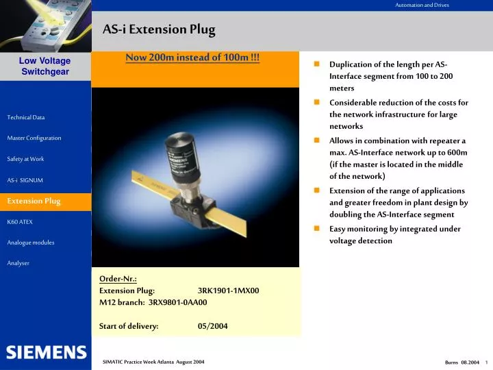
AS-i Extension Plug • Now 200m instead of 100m !!! • Duplication of the length per AS-Interface segment from 100 to 200 meters • Considerable reduction of the costs for the network infrastructure for large networks • Allows in combination with repeater a max. AS-Interface network up to 600m (if the master is located in the middle of the network) • Extension of the range of applications and greater freedom in plant design by doubling the AS-Interface segment • Easy monitoring by integrated under voltage detection Extension Plug • Order-Nr.: • Extension Plug: 3RK1901-1MX00 • M12 branch: 3RX9801-0AA00 • Start of delivery: 05/2004 SIMATIC Practice Week Atlanta August 2004
AS-i Extension Plug Function of the Extension Plug To build a AS-Interface segment longer than 100 m up to 200 m install the extension plug at that point in the network which is most distant to the AS-Interface power supply. It is not necessary to locate this point exactly, as it is sufficient to install the extension plug close to this point (approx. 10 m). Using the extension plug you may build AS-Interface networks in any topology (line, star,tree). You always need just one extension plug per segment even if you use star or tree structure. Depending on the length of a AS-Interface segment and the needed current (depending on the number of connected slaves) you have to consider the voltage drop along the AS-Interface cable. The extension plug is equipped with a under voltage detection for easy monitoring of the AS-Interface voltage. A green LED flashes if the AS-Interface voltage is too low. Extension Plug Ordering data The extension plug has a M12 connection and can be easily connected via the AS-Interface M12 branch 3RX9801-0AA00 in degree of protection IP67. SIMATIC Practice Week Atlanta August 2004
AS-i Extension Plug 200m AS-Interface network with Extension Plug • Easy and cost-effective configuration of AS-Interface segments up to 200 m • Larger dimension without repeater and additional power supply(= reduction of the costs for the network infrastructure) • Configuration in any topology (star, tree, line) Extension Plug SIMATIC Practice Week Atlanta August 2004
AS-i Extension Plug Maximum net expansion with combination of Extension Plug und Repeater • The maximum possible network dimension can be extended by using repeater in combination with the extension plug • Please note that if using the repeater in combination with the extension plug it is not allowed to connect repeaters in series. Therefore, the maximum distance Master Slave is400 m and the absolute maximum distance is 600 m (if the master is located in the middle of the network). • It is possible to connect repeaters in parallel to realize a star topology, each branch with up to 200 m Extension Plug SIMATIC Practice Week Atlanta August 2004
Compact Module K60 for use in explosive atmosphere (ATEX) There are two types of K60 available to use in explosive environment in zone 22 according to classification II 3D (dust atmosphere, non-conductive dust) • Type 4 Inputs/4 OutputsIdentification II 3D T75°C IP65X • Type 4 InputsIdentification II 3D T60°C IP65X • There are special conditions to consider for safe operation !!!Particularly the module has to be protected against mechanical damage by means of suitable protective measures. Further conditions see next page under „special conditions for safe operation“. K60 ATEX • Order-Nr.: • 4E/4A: 3RK1400-1DQ05-0AA3 • 4E: 3RK1200-0CQ05-0AA3 SIMATIC Practice Week Atlanta August 2004
Compact Module K60 for use in explosive atmosphere (ATEX) K60 ATEX • K60 4E module ATEX3RK1200-0CQ05-0AA3 • with safety clip • and manipulation proof sealing cap SIMATIC Practice Week Atlanta August 2004
New AS-Interface Analog Module (profile 7.3) Analog modules with 4 Inputs • new modules up to 4 analog Inputs • more analog signals can be connected with one single module • established K60 housing • preprocessing of the analog values by the AS-i master Order-Nr.: current measurement: 3RK1207-1BQ44-0AA3 voltage measurement: 3RK1207-2BQ44-0AA3 thermal resistance: 3RK1207-3BQ44-0AA3 Fast Analog Value Measurement: • modules with two inputs can be changed over to just one used input • the change over is done via a M12-bridge-connector • using just one input the conversionand transmission time is reducedto one third • conversion and transmission timeto the AS-I master • 1 (used) input: 29 ... 95 ms • 2 (used) inputs: 136 ... 235 ms Analogue Modules Order-Nr.: current 3RK1207-1BQ40-0AA3 voltage 3RK1207-2BQ40-0AA3 thermal resistance 3RK1207-3BQ40-0AA3 M12-bridge-connector 3RK1901-1AA00 SIMATIC Practice Week Atlanta August 2004
ASI Diagnostics made easyASI Analyzer SIMATIC Practice Week Atlanta August 2004
Diagnostics with AS-Interface Lifetime of Installation Commissioning Operation / Maintenance Fault Requirement • Fast fault repair • Documentation • Verification of function and quality • Test protocols for release • Preventive diagnostics • Identification of failed component • Verification of quality • Minimisation of service time • Fast fault repair • Cause of fault • Verification of function • Documentation Solution AS-Interface Analyser System Functions The AS-Interface analyser allows a complete diagnosis of AS-Interface networks during the whole lifetime of the installation. It is the ideal supplement for local diagnostics. SIMATIC Practice Week Atlanta August 2004
EMC FAULT IN COMMISSIONING CONTACTING Slave Parasitic inductions on AS-interface MASTER Slave Slave Slave • Defective Frames can not be detected by analysis of the physical layer • High fault tolerance of AS-interface compensates those faults • Analyser makes preventive diagnostics possible SIMATIC Practice Week Atlanta August 2004
Principle of function - ANALYSER MASTER Slave Slave Slave • RECORD COMMUNICATION: • Interpretation • Record • Represent • Document • Observe Analyser PC SIMATIC Practice Week Atlanta August 2004
Modes STATISTICS TRACE • DETAILED Analysis • Setting trigger conditions • Observe Communication on these conditions • Start the communication record • Detailed Analysis of failures with trace filters • ONLINE ANALYSIS • Simple Overview • Statistic Analysis of Failures • Overview of available Slaves • Representation of Slave Data and IDs „Complete Installation does not work correctly- WHAT IS THE REASON?“ „SIMON with sporadic E-STOPS - WHY?“ SIMATIC Practice Week Atlanta August 2004
Statistic mode: network overview The error rate of available slaves is represented in a simple traffic light function: < 1% Faults per second 1..5 % Faults per second > 5 % Faults per second Slave not projected but present SIMATIC Practice Week Atlanta August 2004
Statistic mode: network overview with hold time • Same look and functionality as network overview • Adjustable hold time for faults • After this hold time, the error rate is evaluated again • Changes in the system are immediately visible SIMATIC Practice Week Atlanta August 2004
Satistic mode: data • All data actually transferred over the network is displayed • Representation without PLC/Host possible • Outputs displayed as process image or as AS-Interface level SIMATIC Practice Week Atlanta August 2004
Statistic mode: configuration • The I/O- and ID-Codes of the slaves are represented SIMATIC Practice Week Atlanta August 2004
Statistic mode: advanced statistics • The data of the overview function is represented numerically here. SIMATIC Practice Week Atlanta August 2004
TRACE mode: Procedure Enter trigger conditions Enter Record filter Offline Supervision of the system RECORDING Download Trace on PC Enter View-Filter ANALYSIS SIMATIC Practice Week Atlanta August 2004
Trace mode: trigger conditions Initiating Trigger Protocol Initiating data Trigger Levels Initiating slave Number of trigger conditions before the next trigger level is activated SIMATIC Practice Week Atlanta August 2004
Trace mode: recording • Recording is started independently from the PC. • Recording can be analysed offline exactly with extensive view filters. • The trigger position (start of recording) is variable SIMATIC Practice Week Atlanta August 2004
Test Protocols • All data of the online statistics can be printed out as Test protocol sheets • The qualitiy of AS-Interface networks can thereby be documented • This allows a verification of the system state for releases or maintenance SIMATIC Practice Week Atlanta August 2004
Advantages / Benefits • The AS-interface analyser allows preventive inspections and therefore maintenance time and down time is reduced considerably • Fast fault repair is rendered possible by the intuitive representation in the statistical mode • Simple and comfortable use makes diagnostics of AS-interface networks possible without a specialist • Inspection sheets give a verification of the state and quality of the system for service and release • Recorded test protocol sheets make remote diagnostics easier by Technical Assistance. Furthermore, any settings of the analyser can be sent in one file per e-mail, whereby outstanding remote diagnostics are achieved • Numerous view filters and trigger functions with physical inputs and outputs make a detailed analysis possible • Process Data is visibleonline and commissionings are thereby accelerated, as it is possible to commission independently of host SIMATIC Practice Week Atlanta August 2004
Technical Data Interfaces AS-Interface RS 232 for interconnection with PC Trigger input (24 V) Trigger output (TTL) Displays / LEDs LED green (power) Supply voltage OK LED green (serial active) RS232 interface in operation LED green/red (test)Test mode Message buffer 256,000 AS-Interface-messagesRated operational current about 70 mA out of AS-InterfaceRated insulation voltage > 500 VEMC according to EN50081-2, EN61000-6-2Ambient air temperature 0°C … +55°CStorage temperature -25°C … +70°CAS-Interface-specification V2.1 SIMATIC Practice Week Atlanta August 2004
Schedule / Ordering data • AS-INTERFACE ANALYSER: • RS232-cable for interconnection with PC • Diagnostics software (CD-ROM) • Order number: 3RK1904-3AB00 • List price: $1750.00 • ACCESSORIES: • AS-Interface branch M12 • 3RX9801-0AA00 • List Price: $13.20 • Cable plug M12 (5m) • 3RX1672 • List Price $15.60 SIMATIC Practice Week Atlanta August 2004