Download
1 / 30
1.14k likes | 2.73k Views
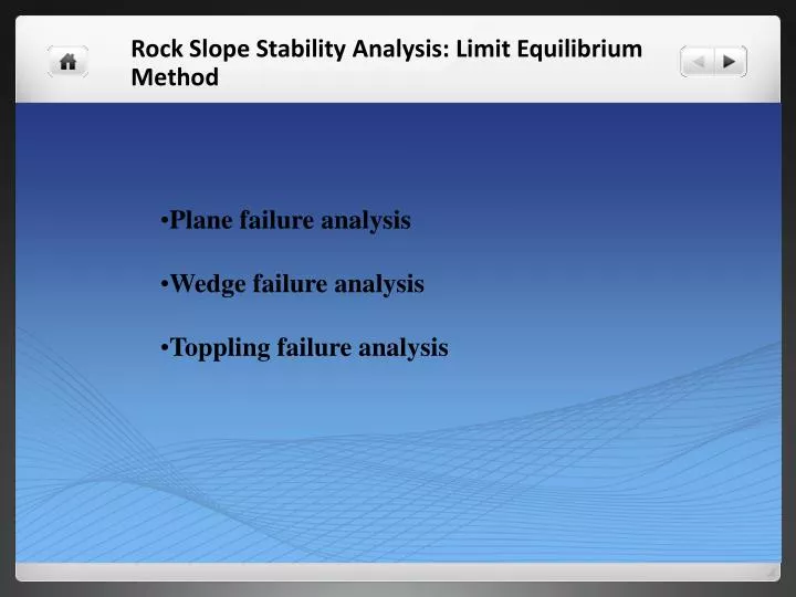
Plane failure analysis Wedge failure analysis Toppling failure analysis . Rock Slope Stability Analysis: Limit Equilibrium Method . The block is considered to undergoes slippage along the plane for the value of ratio < 1, else it is stable. Planar Failure Analysis .

E N D
Plane failure analysis • Wedge failure analysis • Toppling failure analysis Rock Slope Stability Analysis: Limit Equilibrium Method
The block is considered to undergoes slippage along the plane for the value of ratio < 1, else it is stable Planar Failure Analysis A block is rest on a slope having angle θ
C B Unstable Block blockW H W θ α A Plane failure analysis along a discontinuity Geometry of a slope for plane failure
Planar Failure Analysis • the plane on which sliding occurs must strike parallel or nearly parallel (within approximately +200 ) to the slope face • the failure must daylight in the slope face. This means that its dip must be smaller than the dip of the slope face • the dip of the failure plane must be greater than the angle of internal friction angle of this plane Plane failure analysis along a discontinuity
Factor of safety = Factor of safety = = Normal Stress; Factor of safety = Shear Stress , Block A R W sinθ W cosθ W Plane failure analysis along a discontinuity
The effective normal stress due to present of water in the joint, is given as Water is filled in discontinuities
Tension crack present in the upper slope surface Tension crack in upper surface of slope and in the face
Compound slopes have appreciable angle with the horizontal. High slope formation has in generally a positive upper slope angle while the shorter slope has a negative slope angle Compound slope with a positive upper slope angle Compound slope with water in upper slope angle Geometry of slope with tension crack in upper slope angle
Effect of rock bolts Geometry of slope with tension crack in upper slope and its interaction with rock bolt
Wedge Failure Analysis Geometric conditions of wedge failure: (a) pictorial view of wedge failure; (b) stereoplot showing the orientation of the line of intersection
Analysis of wedge failure considering only frictional resistance Resolution of forces to calculate factor of safety of wedge: (a) view of wedge looking at face showing definition of angles β and α, and reactions on sliding Plane RA and RB, (b) stereonet showing measurement of angles β and α, (c) cross- section of wedge showing resolution of wedge weight W.
Analysis of wedge failure with cohesion and friction angle Pictorial View of wedge showing the numbering of intersection lines and planes
Limit equilibrium analysis for toppling failure Model for limiting equilibrium analysis of toppling on a stepped base (Goodman and Bray, 1976).