Download
1 / 44
440 likes | 455 Views
Gaseous Detectors Jan 11, 2019. Gaseous Detectors. Introduction Energy loss (reminder) General principle Principle of operation Drift Time Lorentz Angle Diffusion Amplification Detector Types MWPC Driftchambers Single wire cells Time projection Chamber Resistive Plate Chamber

E N D
Gaseous Detectors Jan 11, 2019
Gaseous Detectors • Introduction • Energy loss (reminder) • General principle • Principle of operation • Drift Time • Lorentz Angle • Diffusion • Amplification • Detector Types • MWPC • Driftchambers • Single wire cells • Time projection Chamber • Resistive Plate Chamber • GridPix chamber • Gas Mixtures • Particle identification
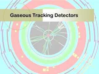
Gaseous detectors are mainly used to measure the trajectory of a charged particle • When a magnetic field is applied the momentum can be determined by measuring the curvature of a particle track
EXAMPLE: ZEUS Drift Chamber Inner radius 16 cm Outer radius 85 cm B-field = 1.5 Tesla 50 MeV 100 MeV andere notatie….. 500 MeV
EXAMPLE: ATLAS Muon Chambers Drift tubes Inner radius 5 m Middle radius 10 m Outer radius 15 m B-field = 0.6 Tesla 5 m 500 GeV Sagitta = 5 mm radius = R Sagitta = L2/8R Sagitta
First Gaseous Detectors • Ionisation chamber Gas filled space with anode and cathode. A current flows after the passage or the absorption of a (possibly charged) particle. V t Discovery of cosmic rays Victor Hess (1912) V
First Gaseous Detectors • Geiger Counter: Hans Geiger, 1908, Manchester [108 years ago!!] wire • Gas ionisation • electron drift • electron avalanche • discharge propagation • (self) quenching
Energy loss • The energy loss depends on the particle and the medium it traverses • Fluctuations in the energy loss follow a Landau distribution
Energy loss • Primary energy loss by ionisation of atoms leads to creation of ion-electron pairs a gas volume. • Two step process: freed electrons can cause secondary ionisation (cluster, delta rays, number of electrons per cluster)
Essential: - number of clusters per mm tracklength - number of electrons per cluster specific for gas(and density ρ, thus T, P!)
dE/dX energy loss np number of clusters/cm nT total number of electrons/cm Z atomic number A atomic mass δ specific density E,W ionisation potentials
General Principle • Electrons drift towards positive anode • Close to the anode the field is strong the electrons are accelerated such that they produces secundary electrons, accelerated such that they produces secundary electrons,accelerated such that they produces secundary electrons, accelerated such that they produces secundary electrons......................an avalanche! • The measured signal is caused by the slow ions moving away from the anode Fernow, page 218-219
First Gaseous Detectors • Geiger Counter: Hans Geiger, 1908, Manchester [108 years ago!!] wire • Gas ionisation • electron drift • electron avalanche • discharge propagation • (self) quenching
Multi Wire Proportional Chamber invented in 1966 by George Charpak (Nobel Prize 1992) Ground V=0 Anode wires at high voltage Ground V=0 Fernow, page 218-219
The signal on the wire provides the coordinate in 1-dimension The resolution is determined by the wire pitch P. No drift time: σ = P /√12 Typical dimension Thickness 10 mm Pitch 2 mm Surface 1000 x 1000 mm Mind the electrostatic force between the two wires Multi Wire Proportional Chamber
Drift of charge • Measuring the time required for an electron (produced by the passage of a charged particle) to drift towards an anode wire provides a measure for the distance between anode wire and point of production (typical measurement accuracy is of the order of a few ns). • For constant electric field the drift velocity is constant. For typical drift fields the drift velocity is in the range of ~ 10 to 100 μm/ns. Fernow, page 212-213
Drift of charge • The electron mobility is much larger than the ion mobility, for example for pure Argon at 1 kV/cm it is • Electrons: 0.4 10-3 cm2V-1m-1s-1 = 400 cm2V-1s-1 for electrons • Argons ions in Argon gas 1.5 cm2V-1m-1s-1 for Ar ions • The mobility depends on the field and (gas) pressure Electrons Fernow, page 212-213
Drift Chamber • After the MWPC introduction of the drift time measurement • To improve the elctric field configuration field wires are used
Single wire cell • The signal is generated by the avalanches close to the wire: The (positive) ion cloud drifts away from the (poistive) wire. • Still the drift time of the primary electrons is visible in the the arrival time distribution: the first electrons that reach the wire come from the nearest point (= the time the particle travels true the cell is neglected).
- Lorentz Angle + B is perp. to image
When a drift field is present the diffusion coefficient in the direction of the field can differ from the diffusion coefficients in the directions perpendicular to the field directions. The drift time is often used for position measurement, therefore the longitudinal diffusion will deteriorate the position resolution. The standard deviation in the drift distance x inferred from the drift time in an electric field for a single electron and due to diffusion is:
5.1.3 Single electron space diffusion per cm of drift in various gases at STP F.Sauli, CERN/EP-2000-108
Gas Gain • The increase in the number of electron after travelling a distance y+dy • The electron multiplication or gain is • The maximum gain is up to 107 Fernow, page 214
Gas Amplification • Positive ions and (negative) electrons start difting under the influence of an electric field. With increasing field we distuinguish: • Ionisation chamber No secundaries or avalanche • Proportional chamber Avalanche but number of ions is proportional to the number of primary ionisations • Geiger counter Avalanches independent of number of primary ionisations • Discharge Continous charge transport (or ‘tripping’, usually unwanted)
Avalanche close to wire F.Sauli, CERN-77-09
Ionisation chambers are used for dosimetry: only the integrated signal over time is relevant (charge collection similar to solid state detectors, see next week) Most particle detectors are in the proportional mode where the total number of secondary electrons is proportional to the number of primary electrons Geiger counter discharges at every single ‘event’ Operation Mode Fernow, page 206
Time Projection Chamber (TPC): 2D/3D Drift Chamber The Ultimate Wire (drift) Chamber track of charged particle E-field (and B-field) Wire plane Wire Plane + Readout Pads Pad plane
Time projection chamber • Measurement of 3-dimensions with high precision • Drift time • Wire signal • Readout pad • No ambiguities or ghost hits • Good pattern recognition in multiple tracks • Long drift times and thus slow readout • If the eventrate is high and the track density is high you get too much free charge in the chamber volume. This can lead to distortion of the E-field.
Time Projection Chamber • Large drift volume of several meters to measure accurate drift time. • Electron drifts parallel to B-field • Avalanche induces signal on sense wires & readout pads Electron drift Avalanche Readout pads Sense wires
Electronics displacement towards sensor: Integration of sensor and electronics
Micro Patterned Gaseous Detectors • High field created by Gas Gain Grids • Most popular: GEM & Micromegas Micromegas improved granularity : wire chambers react on COG of many electron clouds/clusters
Gossip 1 mm GridPix readout of ionisation charge in Time Projection Chamber
He/Isobutane 80/20 Modified MediPix GridPix: the electronic bubble chamber April 2004 14 mm δ-ray! Efficiency for detecting single electrons: < 95 %
Application of Micromegas • New: • pixel chip as active anode readout • MEMS made Micromegas: Integrated Grid InGrid
The MediPix2 pixel CMOS chip 256 x 256 pixels pixel: 55 x 55 μm2 per pixel: - preamp - shaper - 2 discr. - Thresh. DAQ - 14 bit counter - enable counting - stop counting - readout image frame - reset We apply the ‘naked’ MediPix2 chip without X-ray convertor!
Full post-processing of a TimePix • Timepix chip + SiProt + Ingrid: 14 mm MESA+ “Uniform” Charge mode IMT Neuchatel
two beta’s from 90Sr in a 0.2 T B-field 100 GeV Muon in testbeam 2010 @ CERN Particle Detection 9-10 UVA/VU 2002
Inleveren Huiswerk 1 Instrumentatie ! Uploaden voor zondag 7 januari 2018, 16:00 h 1: ga naar de tab 'assignments’ 2: klik op het juiste huiswerk 3: klik op upload en voeg je bestand toe 4: controleer even of er staat dat je een bestand hebt ingeleverd. Er staat als het goed is, als je op de knop assignments drukt, rechts van het desbetreffende huiswerk een 1 in plaats van een 0 bij submissions 5: stel dat je het verkeerde huiswerk hebt ingeleverd of er achterkomt dat je een foutje hebt gemaakt, kan je opnieuw op het desbetreffende huiswerk klikken en de goede/nieuwe versie uploaden indien dit voor de deadline van het desbetreffende huiswerk is. Let er op dat er bijstaat wanneer het huiswerk is ingeleverd, dus achteraf verbeterd huiswerk inleveren werkt niet!