Download
1 / 31
320 likes | 359 Views
Learn about the law of reflection, refraction, Snell's Law, image formation using diverging rays, and thin lenses in geometric optics with examples and strategies. Explore how to find real and virtual images using focal points and magnification.

E N D
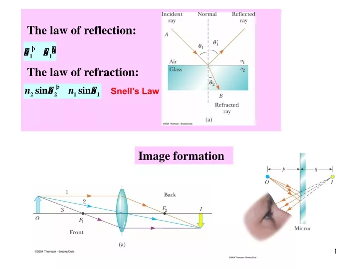
The law of reflection: The law of refraction: Snell’s Law Image formation
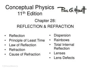
Chapter 23 Ray Optics - Applications: Image Formation
Images are always located by extending diverging rays back to a point at which they intersect • Images are located either at a point from which the rays of light actually diverge or at a point from which they appear to diverge • To find the image it is usually enough to find intersection of just two rays! • Magnification = real image object virtual image
Flat Refracting Surface Snell’s Law Image is always virtual
Chapter 23 Flat mirror
Flat Mirror • One ray starts at point P, travels to Q and reflects back on itself • Another ray follows the path PR and reflects according to the law of reflection • The triangles PQR and P’QR are congruent • . - magnification is 1. always virtual image The law of reflection
Chapter 23 Geometric Optics - Applications: Thin Lenses
Thin Lenses “Thin” means that the width is much smaller than the radius of curvature
Thin Lenses Thin Lens Equation: Object Distance Image Distance Focal Length The thin lens is characterized by only one parameter – FOCAL LENGTH.
Thin Lenses: Focal Length Strategy of Finding f:
Thin Lenses Converging lens Diverging lens They are thickest at the edges They are thickest in the middle
Thin Lenses: Sign Conventions for s, s - + Lateral magnification:
Thin Lenses: Numerical Strategy • Find the focal length f • From the Thin Lens Equation find s’(s is known) • From the sign of s’ find the position of image • Find magnification
Thin Lenses: Focal Points: Converging Lenses • If s>>f, then and • Because light can travel in either direction through a lens, each lens has two focal points. • However, there is only one focal length
Thin Lenses: Focal Points: Diverging Lenses • If s>>f, then and • s’is negative
Converging Lenses For a converging lens, the following three rays (two is enough) are drawn: • Ray 1 is drawn parallel to the principal axis and then passes through the focal point on the back side of the lens • Ray 2 is drawn through the center of the lens and continues in a straight line • Ray 3 is drawn through the focal point on the front of the lens (or as if coming from the focal point if p < ƒ) and emerges from the lens parallel to the principal axis
Converging Lenses: Example 1 • The image is real • The image is inverted • The image is on the back side of the lens
Converging Lenses: Example 2 • The image is virtual • The image is upright • The image is larger than the object • The image is on the front side of the lens
Diverging Lenses • For a diverging lens, the following three rays (two is enough) are drawn: • Ray 1 is drawn parallel to the principal axis and emerges directed away from the focal point on the front side of the lens • Ray 2 is drawn through the center of the lens and continues in a straight line • Ray 3 is drawn in the direction toward the focal point on the back side of the lens and emerges from the lens parallel to the principal axis
Diverging Lenses: Example • The image is virtual • The image is upright • The image is smaller • The image is on the front side of the lens
Image Summary • For a converging lens, when the object distance is greater than the focal length (s > ƒ) • The image is real and inverted • For a converging lens, when the object is between the focal point and the lens, (s < ƒ) • The image is virtual and upright • For a diverging lens, the image is always virtual and upright • This is regardless of where the object is placed
The image formed by the first lens is located as though the second lens were not present • The image of the first lens is treated as the object of the second lens • Then a ray diagram is drawn for the second lens • The image formed by the second lens is the final image of the system • If the image formed by the first lens lies on the back side of the second lens, then the image is treated as a virtual object for the second lens -swill be negative • The overall magnification is the product of the magnification of the separate lenses
Resolution • The ability of optical systems to distinguish between closely spaced objects • If two sources are far enough apart to keep their central maxima from overlapping, their images can be distinguished The images are said to be resolved • If the two sources are close together, the two central maxima overlap and the images are not resolved
Resolution, Rayleigh’s Criterion Rayleigh’s criterion: When the central maximum of one image falls on the first minimum of another image, the images are said to be just resolved Resolution of a slit: • Since λ << a in most situations, sin θ is very small and sin θ ~ θ • Therefore, the limiting angle (in rad) of resolution for a slit of width a is • To be resolved, the angle subtended by the two sources must be greater than
Resolution: Circular Aperture • The diffraction pattern of a circular aperture consists of a central bright disk surrounded by progressively fainter bright and dark rings • The limiting angle of resolution of the circular aperture is • D is the diameter of the aperture The images are unresolved The images are well resolved The images are just resolved