Download
1 / 28
280 likes | 439 Views
Beam Loss Monitoring. Eva Barbara Holzer, CERN CLIC Beam Instrumentation Workshop CERN, June 3, 2009. Beam Loss Monitoring – A Roadmap. How to design the Beam Loss Monitoring System? Collection of requirements Monitor choices Optical Fibers Overview Sensitivity. Design of BLM System.

E N D
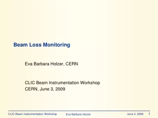
Beam Loss Monitoring Eva Barbara Holzer, CERN CLIC Beam Instrumentation Workshop CERN, June 3, 2009
Beam Loss Monitoring – A Roadmap How to design the Beam Loss Monitoring System? Collection of requirements Monitor choices Optical Fibers Overview Sensitivity
Design of BLM System Required for CDR December 2010: Functional specifications and cost estimate For the cost estimate: • Choice of technology • Investigation of SIL • Possible need for redundant systems
Beam Loss in Standard Operation • Investigate particle loss locations in standard operation • Beam cleaning (collimation, absorbers), aperture limitations, beam dumps, … • Loss locations (spatial and moment distribution at impact) • Simulations (particle tracking) or • Rough determination by looking at apertures, lattice parameters and beam parameters • Watch the color code: • Complete list of tasks (somewhat frightening) • Reduced list of tasks (should be sufficient for CDR)
Beam I Example LHC: Topology of Loss (MQ27.R7) Team R. Assmann Maximum of dispersion and horizontal beta at centre of MQ: Losses start in the dipole and end in the middle of the quadrupole, highest peak at entry of MQ (aperture variations).
Failure Scenarios and Loss Locations • Investigate failure scenarios • Compile exhaustive list of failure scenarios: Magnet failures, collimator failures, kicker misfire, RF failure, power failure, mechanical problems (misalignment, obstacles, ground movement), temperature drift, vacuum problems, computer failures, operation failures, … • Identification of most critical failure scenarios • Loss locations (spatial and moment distribution at impact) • Time development of failure / beam loss: • Onset of the failure • Failure / loss reaches detectability (depends on technology of detection) • Loss reaches dangerous level • Extensive simulations and calculations • Start with the 2-3 most critical ones
Example: Beam Abort Sequence – Fast Beam Loss Based on a graph by R. Schmidt Damage level Beam Losses Beam Dump request could be orders of magnitude Dump threshold 30% of quench level Quench level BLM reading Time Time interval to execute beam abort, min. 2-3 turns 1 turn
Loss Consequences – Limiting conditions I • Investigate limiting condition for each failure scenario and loss location Quantities to consider: • Single shot: • Energy (e.g. heat capacity) • Energy density (e.g. local damage) • Continuous loss: • Power (e.g. global cooling power) • Poser density (e.g. local cooling power)
Loss Consequences – Limiting conditions II 3a) Limits for beam loss: • Mechanical damage to equipment at loss location • E.g. burning hole in vacuum pipe, … • Damage (operation impairment) to equipment further downstream or around – identify the most critical equipment • Impairment of operation • Heat load to equipment (operational range of RF cavity, superconducting wiggler magnets, …) • Radiation (electronics, …)
Loss Consequences – Limiting conditions III 3b) Additional limits for steady state beam loss: • In general covered by separate dosimeter system(s) • Long term radiation damage (insulation material, electronics, …) • Activation issues (access for maintenance, equipment exchange, …) • Extensive simulations (particle showers, heat flow, material damage) and measurements • Simplified (geometry) model simulations (particle showers, heat flow) of the 2-3 most critical failure
Protection Strategy - Choice of Technology • Choice of measurable to determine beam losses (or imminent beam losses) • BLM, fast (magnet) current change monitor, beam current transformer, BPM, transverse tail monitors, … • Resolution required vs achievable • Reaction time required vs achievable • Dynamic range required vs achievable • Investigate SIL (safety integrity level) required and achieved • Need redundant systems for reliability? • Availability still ensured? • Dependability analysis (reliability, availability, maintainability and safety) or • Establish required SIL levels and estimate (based on previous dependability analysis) the SIL levels of various protection system, determine redundant systems when needed. • LHC, 2 month downtime, 30E6CHF repair – >SIL4: E-7 to E-8 failure rate per hour
Protection Strategy – ad ‘system reaction time’ • Time constant of failure development (from onset to dangerous loss): • Passive protection (collimators, absorbers) • Active protection - dump of the pulse tail • Drive beam accelerator: beam dump within < 0.14 ms: might be feasible • Main beam: < 156 ns does not seem feasible • Post pulse analysis (allow following pulse) • 20 ms is comfortable for beam loss measurement
LHC: Beam loss durations classes LOSS DURATION Ultra-fast loss Fast losses Intermediate losses Slow losses Steady state losses PROTECTION SYSTEM Passive Components + BLM (damage and quench prevention) + Quench Protection System, QPS (damage protection only) + Cryogenic System • The BLM is the main active system to prevent magnet damage from all the possible multi-turn beam losses. • Prevention of quench only by BLM system 4 turns (356 s) 10 ms 10 s 100 s
Choice of Technology – ad ‘BLM system’ I • Dynamic range? Given by the range from pilot beam to full intensity. Adjust, so that: • Pilot beam (or low intensity) and no losses observable → extrapolation to full intensity → safely below damage limit; or • Pilot → intermediate; intermediate → full intensity • Compare LHC: 108, two monitor types: 1013 • Distinguish losses from: • Drive beam decelerator vs main beam in same tunnel vs beam transport lines, beam turns, beam dumps • Synchrotron light • Photons from RF cavities • Wigglers, undulators • EM noise • …
Example LHC MQ L. Ponce Distinguish losses from beam 1 and beam 2 Cross-talk signal
Choice of Technology – ad ‘BLM system’ II • Choice of monitor location • Choice of monitor type (sensitive to selective type of radiation: particle species, energy range?) • Can selective timing help to distinguish radiation source? • Thermal neutrons can significantly lengthen the signal (percentage of the signal?) • Simulations to determine secondary particle fluence spectra and time distribution at possible monitor locations • … for the most critical loss scenarios • Simulations to determine monitor response or • Simplified simulations or estimation of approximate monitor response
Example LHC Simulations I M. Stockner MQY LHC quadrupole magnet 7TeV Secondary particle fluence spectrum on the outside recoded in a 3.4 m long stripe, lethargy representation. GEANT4 simulated LHC BLM detector response functions for particle impact direction of 60◦
Example LHC Simulations II M. Stockner Contribution from the different particle types to the signal. Contribution from various particles: domination of photons, protons and pions
CLIC FLUKA Simulation Th. Otto, CLIC Workshop 2008 Simplified model of drive beam and main beam; Loss location: middle of quadrupole. To avoid long term radiation damage (drive beam 2.4 GeV, main beam 1.5 TeV), limit for fractional beam loss : ~< 2 E -7
Main Beam - Preliminary Sophie Mallows 9 GeV 1.5 TeV Same FLUKA simulation set-up. Particle fluence spectra after quadrupoles.
Drive Beam - Preliminary Sophie Mallows 0.24 GeV 2.4 GeV Same FLUKA simulation set-up. Particle fluence spectra after quadrupoles.
Collection of Requirements • Damping Ring: fast BLM to protect superconducting wigglers • Time from loss detection to beam abort : ~ 10 µs desired • Compare LHC: 356 µs (resolution: 40 µs) • Main beam and drive beam: • Dosimetry fractional beam loss : ~< 2 E-7 (long term magnet destruction, simplified FLUKA model) – drive beam 2.4 GeV and main beam 1.5 TeV • Fast BLM fractional beam loss: ~< 1 E-4 (very rough estimate on melting Cu) – main beam 1.5 TeV • Drive beam decelerator • Sensitivity: ~1% of one bunch lost: fractional loss of ~2 E– 8 of one pulse! –3 E-6 of one train • Current meas., precision of <= 0.1% at the start of the lattice and along the lattice with 1%
Recent Developments in Fiber Loss Monitors I Beam Loss and Beam Profile Monitoring with Optical Fibers; F. Wulf, M. Körfer; DIPAC 2009. Dose resolution 3 Gy 60 mGy2 kGy ? Dynamic range ~100 ~30’000 ~500 ?
Recent Developments in Fiber Loss Monitors II Beam Loss and Beam Profile Monitoring with Optical Fibers; F. Wulf, M. Körfer; DIPAC 2009. BLPM (beam loss position measurement); losses generated by inserting OTR screen. Fibres can also be used as detector for wire scanner BPM; two sets of fibres to increase resolution of the beam tails (adapt PMT amplification).
BLM Fibers • Pros: • Cover complete length • Transverse position (and profile) also possible • Time resolution (up to 1 ns) • Minimal space requirement • Insensitive against E and B fields • Radiation hard (depending on type) • Combination fiber / readout can adapt to a wide dose range • Dose measurement • Cons: • Resolution (3 Gy, 60 mGy, 2 kGy ) • Dynamic range (literature: 100, 30’000, 500 - compare LHC: 108, 1013)
Monitor Choices – Estimated Sensitivities Lars Fröhlich, DESY; ERL Instrumentation Workshop 2008. • Diamond, Dosimeter fibers
Summary - Roadmap • Particle loss locations in standard operation • Identification of most critical failure scenarios (loss locations and time development) • Acceptable loss limits for most critical failure scenarios (particle showers, heat flow, material damage) • Choice of measurables and technology: • Resolution • Reaction • Dynamic range • Dependability analysis • Secondary particle fluence spectra and time distribution at possible monitor locations • Determine monitor response • Distinguish radiation sources?