Download
1 / 82
820 likes | 829 Views
Network+ Guide to Networks 5 th Edition. Chapter 7 WANs and Remote Connectivity. Objectives. Identify a variety of uses for WANs Explain different WAN topologies, including their advantages and disadvantages

E N D
Network+ Guide to Networks5th Edition Chapter 7 WANs and Remote Connectivity
Objectives • Identify a variety of uses for WANs • Explain different WAN topologies, including their advantages and disadvantages • Compare the characteristics of WAN technologies, including their switching type, throughput, media, security, and reliability • Describe several WAN transmission and connection methods, including PSTN, ISDN, T-carriers, DSL, broadband cable, TM, and SONET • Describe multiple methods for remotely connecting to a network Network+ Guide to Networks, 5th Edition
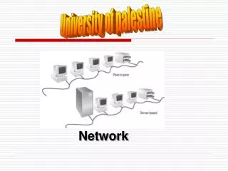
WAN Essentials • WAN • Network traversing some distance, connecting LANs • Transmission methods dependent on business needs • WAN and LAN common properties • Client-host resource sharing, Layer 3 protocols, packet-switched digitized data • WAN and LAN differences • Layers 1 and 2 access methods, topologies, media • LAN wiring: private • WAN wiring: public through NSPs (network service providers) Network+ Guide to Networks, 5th Edition
Figure 7-1 Differences in LAN and WAN connectivity • WAN site • Individual geographic locations • WAN link • WAN site to WAN site connection Network+ Guide to Networks, 5th Edition
WAN Topologies • Differences from LAN topologies • Distance covered, number of users, distance traveled • Connect sites via dedicated, high-speed links • Use different connectivity devices • WAN connections • Require Layer 3 devices • Routers • Not capable of nonroutable protocols Network+ Guide to Networks, 5th Edition
Bus • Each site connects to two sites maximum serially • Similar LAN topology site dependency • Network site dependent on every other site to transmit and receive traffic • Difference from LAN topology • Different locations connected to another through point-to-point links • Best use • Organizations requiring small WAN, dedicated circuits • Drawback • Not scalable Network+ Guide to Networks, 5th Edition
Figure 7-2 A bus topology WAN Bus (cont’d.) Network+ Guide to Networks, 5th Edition
Ring • Each site connected to two other sites • Forms ring pattern • Similar to LAN ring topology • Differences from LAN ring topology • Connects locations • Relies on redundant rings • Data rerouted upon site failure • Expansion • Difficult, expensive • Best use • Connecting four, five locations maximum Network+ Guide to Networks, 5th Edition
Figure 7-3 A ring topology WAN Ring (cont’d.) Network+ Guide to Networks, 5th Edition
Star • Mimics star topology LAN • Single site central connection point • Separate data routes between any two sites • Advantages • Single connection failure affects one location • Different from bus, star topology • Shorter data paths between any two sites • When all dedicated circuits functioning • Expansion: simple, less costly • Drawback • Central site failure Network+ Guide to Networks, 5th Edition
Figure 7-4 A star topology WAN Star (cont’d.) Network+ Guide to Networks, 5th Edition
Mesh • Incorporates many directly interconnected sites • Data travels directly from origin to destination • Routers can redirect data easily, quickly • Most fault-tolerant WAN type • Full-mesh WAN • Every WAN site directly connected to every other site • Drawback: cost • Partial-mesh WAN • Reduce costs Network+ Guide to Networks, 5th Edition
Figure 7-5 Full-mesh and partial-mesh WANs Mesh (cont’d.) Network+ Guide to Networks, 5th Edition
Tiered • Sites connected in star or ring formations • Interconnected at different levels • Interconnection points organized into layers • Form hierarchical groupings • Flexibility • Allows many variations, practicality • Requires careful considerations: • Geography, usage patterns, growth potential Network+ Guide to Networks, 5th Edition
Figure 7-6 A tiered topology WAN Tiered (cont’d.) Network+ Guide to Networks, 5th Edition
PSTN • PSTN (Public Switched Telephone Network) • Network of lines, carrier equipment providing telephone service • POTS (plain old telephone service) • Encompasses entire telephone system • Originally: analog traffic • Today: digital data, computer controlled switching • Dial-up connection • Used early on • Modem connects computer to distant network • Finite time period Network+ Guide to Networks, 5th Edition
PSTN (cont’d.) • PSTN elements • Cannot handle digital transmission • Requires modem • Signal travels path between modems • Over carrier’s network • Includes CO (central office), remote switching facility • Signal converts back to digital pulses • CO (central office) • Where telephone company terminates lines • Switches calls between different locations Network+ Guide to Networks, 5th Edition
Figure 7-7 A long-distance dial-up connection Network+ Guide to Networks, 5th Edition
Figure 7-8 Local loop portion of the PSTN • Local loop (last mile) • Portion connecting residence, business to nearest CO • Most likely uses copper wire, carries analog signal Network+ Guide to Networks, 5th Edition
PSTN (cont’d.) • Demarcation point • Local loop endpoint • Carriers responsibility ends • Wires terminate at NIU (network interface unit) • PSTN Internet connection advantage • Ubiquity, ease of use, low cost • PSTN disadvantage • Some circuit switching used • Marginal security Network+ Guide to Networks, 5th Edition
X.25 and Frame Relay • X.25 ITU standard • Analog, packet-switching technology • Designed for long distance • Original standard: mid 1970s • Mainframe to remote computers: 64 Kbps throughput • Update: 1992 • 2.048 Mbps throughput • Client, servers over WANs • Verifies transmission at every node • Excellent flow control, ensures data reliability • Slow and unreliable for time-sensitive applications Network+ Guide to Networks, 5th Edition
X.25 and Frame Relay (cont’d.) • Frame relay • Updated X.25: digital, packet-switching • Protocols operate at Data Link layer • Supports multiple Network, Transport layer protocols • Both perform error checking • Frame relay: no reliable data delivery guarantee • X.25: errors fixed or retransmitted • Throughput • X.25: 64 Kbps to 45 Mbps • Frame relay: customer chooses Network+ Guide to Networks, 5th Edition
X.25 and Frame Relay (cont’d.) • Both use virtual circuits • Based on potentially disparate physical links • Logically appear direct • Advantage: efficient bandwidth use • Both configurable as SVCs (switched virtual circuits) • Connection established for transmission, terminated when complete • Both configurable as PVCs (permanent virtual circuits) • Connection established before transmission, remains after transmission Network+ Guide to Networks, 5th Edition
X.25 and Frame Relay (cont’d.) • PVCs • Not dedicated, individual links • X.25 or frame relay lease contract • Specify endpoints, bandwidth • CIR (committed information rate) • Minimum bandwidth guaranteed by carrier • PVC lease • Share bandwidth with other X.25, frame relay users Network+ Guide to Networks, 5th Edition
X.25 and Frame Relay (cont’d.) • Frame relay lease advantage • Pay for bandwidth required • Less expensive technology • Long-established worldwide standard • Frame relay and X.25 disadvantage • Throughput variability • Due to shared lines • Frame relay and X.25 easily upgrade to T-carrier dedicated lines • Due to same connectivity equipment Network+ Guide to Networks, 5th Edition
Figure 7-9 A WAN using frame relay X.25 and Frame Relay (cont’d.) Network+ Guide to Networks, 5th Edition
ISDN • Digital data transmitted over PSTN • Gained popularity: 1990s • Connecting WAN locations • Exchanges data, voice signals • Protocols at Physical, Data Link, Transport layers • Signaling, framing, connection setup and termination, routing, flow control, error detection and correction • Relies on PSTN for transmission medium • Dial-up or dedicated connections • Dial-up relies exclusively on digital transmission Network+ Guide to Networks, 5th Edition
ISDN (cont’d.) • Single line • Simultaneously: two voice calls, one data connection • Two channel types • B channel: “bearer” • Circuit switching for voice, video, audio: 64 Kbps • D channel: “data” • Packet-switching for call information: 16 or 64 Kbps • BRI (Basic Rate Interface) connection • PRI (Primary Rate Interface) connection Network+ Guide to Networks, 5th Edition
Figure 7-10 A BRI link • BRI: two B channels, one D channel (2B+D) • B channels treated as separate connections • Carry voice and data • Bonding • Two 64-Kbps B channels combined • Achieve 128 Kbps Network+ Guide to Networks, 5th Edition
Figure 7-11 A PRI link • PRI: 23 B channels, one 64-Kbps D channel (23B+D) • Separate B channels independently carry voice, data • Maximum throughput: 1.544 Mbps • PRI and BRI may interconnect Network+ Guide to Networks, 5th Edition
T-Carriers • T1s, fractional T1s, T3s • Physical layer operation • Single channel divided into multiple channels • Using TDM (time division multiplexing) over two wire pairs • Medium • Telephone wire, fiber-optic cable, wireless links Network+ Guide to Networks, 5th Edition
Table 7-1 Carrier specifications Types of T-Carriers • Many available • Most common: T1 and T3 Network+ Guide to Networks, 5th Edition
Types of T-Carriers (cont’d.) • T1: 24 voice or data channels • Maximum data throughput: 1.544 Mbps • T3: 672 voice or data channels • Maximum data throughput: 44.736 Mbps (45 Mbps) • T-carrier speed dependent on signal level • Physical layer electrical signaling characteristics • DS0 (digital signal, level 0) • One data, voice channel Network+ Guide to Networks, 5th Edition
Types of T-Carriers (cont’d.) • T1 use • Connects branch offices, connects to carrier • Connects telephone company COs, ISPs • T3 use • Data-intensive businesses • T3 provides 28 times more throughput (expensive) • Multiple T1’s may accommodate needs • TI costs vary by region • Fractional T1 lease • Use some T1 channels, charged accordingly Network+ Guide to Networks, 5th Edition
T-Carrier Connectivity • T-carrier line requires connectivity hardware • Customer site, switching facility • Purchased or leased • Cannot be used with other WAN transmission methods • T-carrier line requires different media • Throughput dependent Network+ Guide to Networks, 5th Edition
T-Carrier Connectivity (cont’d.) • Wiring • Plain telephone wire • UTP or STP copper wiring • STP preferred for clean connection • Coaxial cable, microwave, fiber-optic cable • T1s using STP require repeater every 6000 feet • Multiple T1s • Coaxial cable, microwave, fiber-optic cabling • T3s require microwave, fiber-optic cabling Network+ Guide to Networks, 5th Edition
Figure 7-12 A T1 smart jack • Smart Jack • Terminate T-carrier wire pairs • Customer’s demarc (demarcation point) • Inside or outside building • Connection monitoring point Network+ Guide to Networks, 5th Edition
T-Carrier Connectivity (cont’d.) • CSU/DSU (Channel Service Unit/Data Service Unit) • Two separate devices • Combined into single stand-alone device • Interface card • T1 line connection point • At customer’s site • CSU • Provides digital signal termination • Ensures connection integrity Network+ Guide to Networks, 5th Edition
Figure 7-13 A CSU/DSU T-Carrier Connectivity (cont’d.) • DSU • Converts T-carrier frames into frames LAN can interpret (vice versa) • Connects T-carrier lines with terminating equipment • Incorporates multiplexer Network+ Guide to Networks, 5th Edition
Figure 7-14 A point-to-point T-carrier connection T-Carrier Connectivity (cont’d.) • Incoming T-carrier line • Multiplexer separates combined channels • Outgoing T-carrier line • Multiplexer combines multiple LAN signals Network+ Guide to Networks, 5th Edition
T-Carrier Connectivity (cont’d.) • Terminal Equipment • Switches, routers, bridges • Best option: router, Layer 3 or higher switch • Accepts incoming CSU/DSU signals • Translates Network layer protocols • Directs data to destination • CSU/DSU may be integrated with router, switch • Expansion card • Faster signal processing, better performance • Less expensive, lower maintenance solution Network+ Guide to Networks, 5th Edition
Figure 7-15 A T-carrier connecting to a LAN through a router T-Carrier Connectivity (cont’d.) Network+ Guide to Networks, 5th Edition
DSL • DSL (digital subscriber line) • Operates over PSTN • Directly competes with ISDN, T1 services • Requires repeaters for longer distances • Best suited for WAN local loop • Supports multiple data, voice channels • Over single line • Higher, inaudible telephone line frequencies • Uses advanced data modulation techniques • Data signal alters carrier signal properties • Amplitude or phase modulation Network+ Guide to Networks, 5th Edition
Types of DSL • xDSL refers to all DSL varieties • ADSL, G.Lite, HDSL, SDSL, VDSL, SHDSL • Two DSL categories • Asymmetrical and symmetrical • Downstream • Data travels from carrier’s switching facility to customer • Upstream • Data travels from customer to carrier’s switching facility Network+ Guide to Networks, 5th Edition
Types of DSL (cont’d.) • Downstream, upstream throughput rates may differ • Asymmetrical • More throughput in one direction • Downstream throughput higher than upstream throughput • Best use: video conferencing, web surfing • Symmetrical • Equal capacity for upstream, downstream data • Examples : HDSL, SDSL, SHDSL • Best use: uploading, downloading significant data amounts Network+ Guide to Networks, 5th Edition
Table 7-2 Comparison of DSL types Types of DSL (cont’d.) • How DSL types vary • Data modulation techniques • Capacity • Distance limitations • PSTN use Network+ Guide to Networks, 5th Edition
Figure 7-16 A DSL modem DSL Connectivity • ADSL: common example on home computer • Establish TCP connection • Transmit through DSL modem • Internal or external • Splitter separates incoming voice, data signals • May connect to hub, switch, router Network+ Guide to Networks, 5th Edition
DSL Connectivity (cont’d.) • ADSL (cont’d.) • DSL modem forwards modulated signal to local loop • Signal continues over four-pair UTP wire • Distance less than 18,000 feet: signal combined with other modulated signals in telephone switch • Carrier’s remote switching facility • Splitter separates data signal from voice signals • Request sent to DSLAM (DSL access multiplexer) • Request issued from carrier’s network to Internet backbone Network+ Guide to Networks, 5th Edition
Figure 7-17 A DSL connection DSL Connectivity (cont’d.) Network+ Guide to Networks, 5th Edition
DSL Connectivity (cont’d.) • DSL competition • T1, ISDN, broadband cable • DSL installation • Hardware, monthly access costs • Slightly less than ISDN, significantly less than T1s • DSL drawbacks • Not available in all areas • Upstream throughput lower than broadband cable • Consumers use broadband Internet access service Network+ Guide to Networks, 5th Edition