Download
1 / 65
650 likes | 953 Views
Lecture 7. Disc Scheduling. Lecture Highlights. Introduction to Disc Management Need for disc scheduling Disc Structure Details of disc speed Disc Scheduling Algorithms Parameters Involved Parameter-Performance Relationships Some Sample Results. Introduction to Disc Management.

E N D
Lecture 7 Disc Scheduling
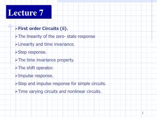
Lecture Highlights • Introduction to Disc Management • Need for disc scheduling • Disc Structure • Details of disc speed • Disc Scheduling Algorithms • Parameters Involved • Parameter-Performance Relationships • Some Sample Results
Introduction to Disc Management • Disk systems are the major secondary-storage I/O device on most computers. • One of the functions of the memory manager is to manage swapping between main memory and disk when main memory is not big enough to hold all the processes. • The disk, i.e. the secondary storage device, at the same time needs effective management in terms of disc structure and capacity, the disc writing mechanism and the scheduling algorithm choice.
Introduction to Disc ManagementNeed for disc scheduling • Requests for disk I/O are generated both by the file system and by virtual-memory systems. • Since most jobs depend heavily on the disc for program loading and input and output files, it is important that disk service be as fast as possible. • The operating system can improve on the average disk service time by scheduling the requests for disc access.
Introduction to Disc ManagementDisc Structure • A disc can be viewed as a set of platters on top of each other. • Each platter has two surfaces. • Each surface is divided into tracks which are concentric. • Each track is further divided into a number of sectors. • A sector is the smallest unit of information that can be read from or written to the disc. In other words, a sector is the smallest addressable portion of the disc. Hard Disc Structure: tracks platters sectors spindle read-write heads
Introduction to Disc ManagementDisc Structure • To access a sector – surface, track and sector need to be specified i.e. information on the disc is referenced by a multipart address, which includes the drive number, the surface, the track, and the sector. • All the tracks on one drive that can be accessed without the heads being moved (the equivalent tracks on the different surfaces) constitute a cylinder. • Each track has equal capacity which means that inner tracks are more densely coated. This allows the read-write head to have the same velocity over each track.
Introduction to Disc ManagementDisc Structure • Sectors vary from 32 bytes to 4096 bytes; usually, they are 512 bytes in size. • There are 20 to 1500 tracks per disc surface. • I/O transfers between memory and disc are performed in units of one or more sectors, called blocks, to improve I/O efficiency.
Introduction to Disc ManagementDetails of disc speed • The disk movement is composed of three parts. • The three distinct physical operations, each with its own cost, are: • seek time • rotational delay/latency time • transfer time. • After looking into the three operations in some more details, specifications of three disc drives from past and present are included to give you a realistic idea of the concerned parameters and how the technology has been advancing.
Details of disc speedSeek Time • To access a block on the disk the system must first move the head to the appropriate track or cylinder. • This head movement is called a seek, and the time to complete it is seek time. • The amount of time spent seeking during a disc access depends on how far the arm has to move (more explanation follows on the next slide).
Details of disc speedSeek Time • If we are accessing a file sequentially and the file is packed into several consecutive cylinders, seeking needs to be done only after all the tracks on a cylinder have been processed, and then the read/write head needs to move the width of only one track (minimum seek time/ track-to-track seek time). • At the other extreme, if we are alternately accessing sectors from two files that are stored at opposite extremes on a disk, seeking is very expensive (could be full stroke/ max seek time). • Consequently, if we were to write to an empty disc, it is more efficient to do the writing cylinder wise as it reduces seek time.
Details of disc speedSeek Time • Seeking is likely to be more costly in a multi-user environment, where several processes are contending for use of the disk at one time, than in a single-user environment, where disk usage is dedicated to one process. This is so because in a multi-user environment the different users might be seeking files at different locations. • Since seeking can be very costly, system designers often go to great extremes to minimize seeking. In an application that merges three files, for example, it is not unusual to see the three input files stored on three different drives and the output file stored on a fourth drive, so no seeking need be done as I/O operations jump from file to file.
Details of disc speedSeek Time • Since it is usually impossible to know exactly how many tracks will be traversed in a seek, we usually try to determine the average seek time required for a particular operation. • If the starting and ending positions for each access is random, it turns out that the average seek traverses one-third of the total number of cylinders that the read/write head ranges over. • Most hard discs available today have average seek times of less than 10ms and high performance discs have average seek times as low as 7.5ms.
Details of disc speedLatency Time / Rotational Delay • Once the head is at the right track, it must wait until the desired block rotates under the read-write head. This delay is the latency time. • Hard discs usually rotate at about 5000 rpm, which is one revolution per 12ms. • On average, the rotational delay is half a revolution, or about 6ms. • As in the case of seeking, these averages apply only when the read/write head moves from some random place on the disc surface to the target track. In many circumstances, rotational delay can be much less than the average.
Details of disc speedTransfer Time • Once the data we want is under the read/write head, it can be transferred . The transfer time is given by the formula: Transfer time = number of bytes transferredX rotation time number of bytes on a track • If a disc is sectored, the transfer time for one sector depends on the number of sectors on a track. For example, if there are 63 sectors per track, the time required to transfer one sector would be 1/63 of a revolution.
Details of disc speedSample specifications of discs (from past)
Details of disc speedSample specifications of discs (at present)
Introduction to Disc ManagementSummary of disc speed • The total time to service a disk request is the sum of the seek time, latency time, and transfer time. • For most disks the seek time dominates, so reducing the mean seek time can improve the system performance substantially. • Thus, the primary concern of disc scheduling algorithms is to minimize seek and latency times.
Disc Scheduling AlgorithmsFirst Come First Serve (FCFS) • FCFS is the simplest form of disc scheduling • This algorithm is easy to program and is intrinsically fair. • However, it may not provide the best service. • The example on the next page illustrates FCFS scheduling.
Disc Scheduling AlgorithmsFirst Come First Serve (FCFS) • Suppose an ordered disc queue with requests involving tracks 98, 183, 37, 122, 14, 124, 65, 67 • If the read-write head is initially at track 53, it will first move to 98, then to 183, 37, 122, 14, 124, 65 and finally to 67 (as depicted by the figure on the next slide). • In this case, total head movement = 640 tracks.
queue = 98, 183, 37, 122, 14, 124, 65, 67 head starts at 53 0 14 37 53 65 67 98 122 124 183 199 Disc Scheduling AlgorithmsFirst Come First Serve (FCFS)
Disc Scheduling AlgorithmsShortest Seek Time First (SSTF) • The SSTF algorithm selects the request with the minimum seek time from the current head position. • Since seek time is generally proportional to the track difference between the requests, this approach is implemented by moving the head to the closest track in the request queue. • We’ll use the same sequence of requests as used in the FIFO example to illustrate SSTF scheduling.
Disc Scheduling AlgorithmsShortest Seek Time First (SSTF) • Suppose an ordered disc queue with requests involving tracks 98, 183, 37, 122, 14, 124, 65, 67 • If the read-write head is initially at track 53, it will first move to 65, then to 67, 37, 14, 98, 122, 124, and finally to 183 (as depicted by the figure on the next slide). • In this case, total head movement = 236 tracks. • SSTF results in a substantial improvement in average disk service but suffers from the potential of starvation (specially in case of dynamic requests).
queue = 98, 183, 37, 122, 14, 124, 65, 67 head starts at 53 0 14 37 53 65 67 98 122 124 183 199 Disc Scheduling AlgorithmsShortest Seek Time First (SSTF)
Disc Scheduling AlgorithmsSCAN Scheduling • The read-write head starts at one end of the disc, and moves toward the other end, servicing requests as it reaches each track, until it gets to the other end of the disc. At the other end, the direction of head movement is reversed and servicing continues. • The head continuously scans the disc from end to end. • SCAN algorithm is also called the elevator algorithm. • Lets apply this algorithm to the same example.
Disc Scheduling AlgorithmsSCAN Scheduling • We’ll use the same request sequence 98, 183, 37, 122, 14, 124, 65, 67 • If the read-write head is initially at track 53 moving towards 0, it will first service 37 and 14, change directions and service 65, 67, 98, 122, 124, and finally 183 (as depicted by the figure on the next slide). • Moreover, if a request arrives in the queue just in front of the head, it will be serviced almost immediately. • However, if a request arrives in the queue just behind the head it will have to wait for almost two full cycles.
queue = 98, 183, 37, 122, 14, 124, 65, 67 head starts at 53 0 14 37 53 65 67 98 122 124 183 199 Disc Scheduling AlgorithmsSCAN Scheduling
Disc Scheduling AlgorithmsC-SCAN Scheduling • A variant of SCAN scheduling that is designed to provide a more uniform wait time is C-SCAN (circular SCAN) scheduling. • As does SCAN scheduling C-SCAN scheduling moves the head from one end of the disc to the other, servicing requests as it goes. • When it reaches the other end, however, it immediately returns to the beginning of the disc, without servicing any requests on the return trip. • The C-SCAN algorithm essentially treats the disc as though it were circular, with the last track adjacent to the first one.
Disc Scheduling AlgorithmsC-SCAN Scheduling • Lets take a look at the processing of our request queue: 98, 183, 37, 122, 14, 124, 65, 67 in this case. • The order of processing starting at 53 would be 65, 67, 98, 122, 124, 183, 14 and 37 (as depicted by the figure on the next slide).
queue = 98, 183, 37, 122, 14, 124, 65, 67 head starts at 53 0 14 37 53 65 67 98 122 124 183 199 Disc Scheduling AlgorithmsC-SCAN Scheduling
Disc Scheduling AlgorithmsLOOK and C-LOOK Scheduling • Both SCAN and C-SCAN scheduling always move the head from one end of the disk to the other. • In practice, neither algorithm is implemented in this way. • More commonly, the head is only moved as far as the last request in each direction. As soon as there are no requests in the current direction, the head movement is reversed. • These versions of SCAN and C-SCAN scheduling are called LOOK and C-LOOK scheduling (see figure on next slide).
queue = 98, 183, 37, 122, 14, 124, 65, 67 head starts at 53 0 14 37 53 65 67 98 122 124 183 199 Disc Scheduling AlgorithmsC-LOOK Scheduling
Disc Scheduling AlgorithmsSelecting a disc scheduling algorithm • With any scheduling algorithm, performance depends heavily on the number and types of requests. • If the queue seldom has more than one outstanding request, then all scheduling algorithms are effectively equivalent and FIFO would be a reasonable choice. • The SCAN and C-SCAN algorithms are more appropriate for systems that place a heavy load on the disc.
Parameter Involved • Disc access time (seek time, latency time and transfer time) • Disc configuration • Disc scheduling algorithm • Disc writing mechanism (where to rewrite processes after processing them in RAM) • Disc capacity
Parameter InvolvedEffect of Disc Access Time • The lower is the value of this parameter, the better is the system performance. • As explained earlier in the lecture, seek time, latency time and transfer time together give the disc access time. • Since seek is the most expensive of the three operations, lowering seek time is crucial to system efficiency.
Parameter InvolvedEffect of Disc Configuration • Disk configuration relates to the structural organization of the disc into tracks and sectors. Disc surfaces and tracks are determined by hardware specifications. • However, some operating systems allow the user to choose the sector size that influences the number of sectors per track. It is an entire sector that is read or written when transfer occurs. • The number of tracks equals the number of cylinders. Reading and writing on one cylinder reduces the seek time considerably. • This property determines efficiency of many computing algorithms and determines inter-record and intra-record fragmentation in terms of database operations • It also affects system performance in operations like disc defragmentation ( a rewriting mechanism).
Parameter InvolvedEffect of Disc Scheduling Algorithm • This is the parameter that primarily determines the possible minimization of seek and latency times. • While FCFS algorithm is easy to program and is intrinsically fair, however, it may not provide the best service. • SSTF scheduling substantially improves the average service time but suffers from the inherent problem of starvation of certain processes in case of continuing/dynamic flow of requests.
Parameter InvolvedEffect of Disc Scheduling Algorithm • The SCAN, C-SCAN, LOOK and C-LOOK belong to the more efficient genre of disk scheduling algorithms. These are however, complicated in their respective implementations and are more appropriate for systems that place a heavy load on the disk. With any scheduling algorithm, however, performance depends heavily on the number and types of requests. • In particular, if the queue seldom has more than one outstanding request, then all scheduling algorithms are effectively equivalent. In this case, FCFS scheduling is also a reasonable algorithm.
Parameter InvolvedEffect of Disk Writing Mechanism • In terms of disk writing mechanism, there is a choice between writing back to where the process was initially read from and writing back to the closest cylinder to the disk head where there is an empty sector. • While the former is straightforward to implement in no way does it attempt an optimization of seek time. • The latter choice, however, results in increased overhead in terms of updating the location of the process every time it is written back to the disk.
Performance Measures • Average Waiting Time • Average Turnaround Time • CPU utilization • CPU throughput • Percentage seek time • This is a new performance measure and it quantifies latency cost • Calculated as a percentage of total time • Percentage latency time • This is a new performance measure and it quantifies latency cost • Calculated as a percentage of total time
Disc SchedulingImplementation • As part of Assignment 5, you’ll implement a memory manager system including a Disc simulator within an operating system satisfying the given requirements. (For complete details refer to Assignment 5) • We’ll see a brief explanation of the assignment in the following slides.
Disc SchedulingImplementation Details Following are some specifications of the system you’ll implement: • You’ll use the memory and job mix description in Assignment 3 • Disc access time = Seek + Latency + (job size(in bytes) / 500000) ms (Transfer time) ( you’ll recall that in Assignment 3 we had used a constant value of 1ms instead of seek and latency times but here the same shall be a variable and you could study the effect of it on system performance) • Disc has eight surfaces, 300 tracks/surface • Use your own latency and seek time rates (should be a program variable) • Make the Disc Scheduling mechanism a variable (SSTF/ FIFO / ..etc.)
Disc SchedulingImplementation Details After completing the implementation and doing a few sample runs, start thinking of this problem from an algorithmic design point of view. The algorithm/hardware implementation of the memory manager/Disc manager involves many parameters, some of them include: • Memory Size • Disc access time (transfer time, latency and seek) • Time slot for RR • Compaction thresholds (percentage and hole size) • RAM access time (Continued on the next slide)
Disc SchedulingImplementation Details Some of the involved parameters (continued from the last slide): • Fitting algorithm • Disc Scheduling algorithm choice (FIFO, SSTF, SCAN, LOOK, etc.) • Disc structure and capacity (surfaces, tracks, etc.) • Disc writing mechanism (where to write back processed pages)
Disc SchedulingImplementation Details The eventual goal would be to optimize several (or some) performance measures (criteria) such as: • Average waiting time • Average turnaround time • Maximum waiting time • Maximum turnaround time • CPU utilization • CPU throughput • Memory fragmentation over time • Disc fragmentation over time
Disc SchedulingImplementation Details After you are done with the assignment, you have the opportunity to attempt the following two bonus questions: • Bonus Question 1: Implement the above using a paging mechanism (1-level) (I.e. divide each jobs to a number of pages, given a fixed page size). Implement a page replacement algorithm (or more) to decide which pages to replace and to anticipate page usage throughout the simulation. You have to implement a randomizer to simulate page access patterns for different processes. Try different dynamic algorithms for deciding on the number of memory pages to be assigned to a process through the life of a process in the system (dynamically).
Disc SchedulingImplementation Details • Bonus Question 2: Study and analyze the behavior of the combined memory system and Disc (the performance measures) based on parameter changes as above and incorporate the following parameters: • Page Size • Page replacement and paging anticipation algorithm choice • Disc writing algorithm choice (how and where to write jobs back to disc)
Disc SchedulingSample Screenshots of Simulation Setting variable parameters
Disc SchedulingSample Screenshots of Simulation Setting variable parameters (contd.)
Disc SchedulingSample Screenshots of Simulation Initial Hard Disc Configuration
Disc SchedulingSample Screenshots of Simulation Initial RAM Configuration