Download
1 / 85
900 likes | 1.2k Views
BASIC ROADSIDE DESIGN CONCEPTS. Thomas R. Bane P.E. 605 Suwannee Street Mail-station 32 Tallahassee Florida 32399 (850) 414-4379 thomas.bane@dot.state.fl.us. Rural Facilities. Rural Roadways 1910-1954. Rural Roadways 1954-2003. Urban Facilities. Urban Roadways 1890-1910.

E N D
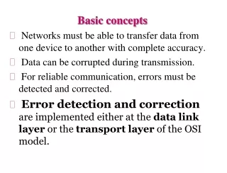
BASIC ROADSIDE DESIGN CONCEPTS Thomas R. Bane P.E. 605 Suwannee Street Mail-station 32 Tallahassee Florida 32399 (850) 414-4379 thomas.bane@dot.state.fl.us
Urban Roadways 1890-1910 MONROE STREET & COLLEGE AVE WHO KNOWS WHERE
Urban Roadways 1937-1954 1937 AASHO guidance “use common sense”
Urban Roadways 1954-1973 1973 AASHO “A Policy on Geometric Design of Urban Highways and Arterial Streets” “30-foot clear area to be provided in urban and suburban sections but made exceptions to residential areas. 1967 SRD adopts by memorandum “Design Criteria related to Highway Safety” “30-foot clear recovery area for flush shoulders…” 1967 SRD adopts by memorandum “Design Criteria related to Highway Safety” “30-foot clear recovery area for flush shoulders and a 4-foot “clear recovery area in curbed sections” 1954 AASHO “A Policy on Geometric Design of Rural Highways” no guidance for urban areas usually 2’ to 4’ was being provided. 1967 AASHO “Highway Design and Operational Practices related to Highway Safety” “30-foot unencumbered recovery area” or “clear recovery area”
Urban Roadways 1973-1982 1973 AASHO “A Policy on Geometric Design of Urban Highways and Arterial Streets” “30-foot clear area to be provided in urban and suburban sections but made exceptions to residential areas. 1982 FDOT “Old Standard Index 700” “30-foot clear recovery area for flush shoulders and a 4-foot “clear recovery area in curbed sections”
Exhibit 23-C Design Exceptions 1 1
Utility Exceptions FUCC & FDOT Chapter 13 Utility Exceptions Added In 1999 1994-1999 Last Update 1993 4 Critical Elements A Vertical Clearance B Horizontal Clearance C Limited Access R/W use D Control Zone Use
Problems & Misperceptions
National Crash Distribution Pole/Post Bridge 14% 19% Guardrail 4% Culv/Curb/Ditch 26% 10% Embankment 17% 10% Trees Other
Curb & Gutter Misperceptions
Correcting Some Misconceptions 6” 5” Type-E curb Type-F curb Mountable Non-mountable
LOW PROFILE BARRIER 18” Redirective Correcting Some Misconceptions 6” 5” Type-E curb Type-F curb Sloping Sloping
FDOT Type E&F Curb Misperceptions: Do : Don’t : • Channel water • Provide delineation • Discourage drivers from driving over them • Act as barriers • Slow vehicles • Redirect vehicles Horizontal Clearances Practices: Flush Shoulder = Clear Zone Curb and Gutter = 4-foot Restricted Areas = Offsets based on function Non-restricted Areas = Offsets based on Clear Zone
Urban/Suburban/Rural Problems
1954 Suburban Highways 2002
Design Speed = 70mph Friction Course FC-5 200 feet NON-RESTRICTED SR 500 - Clear Zone to be provided
Design Speed = 45mph Friction Course FC-6 106 feet RESTRICTED Wilson St. - Clear Zone not provided
Design Speed = 55mph Friction Course FC-5 148 feet NON-RESTRICTED Sara Ave. - Clear Zone to be provided
Implementing a New Criteria Control Zones • Areas that historically have a high probability of crashes. • Designated areas where New Construction Criteria is used in lieu of RRR Criteria.
Problems with Determining Clear Zones
+ Clear Runout Minimum Clear Zone = 30 feet Minimum Recoverable Terrain = 30 feet 46’ 10’ 22’ Non- Recoverable R/W Clear Runout Clear Zone = 30’ Clear Zone = 40’
Clear Zone Non-Recoverable Terrain Recoverable Terrain Recoverable Terrain Edge of Lane Shoulder R/W Slope 1:4 or flatter Slope steeper than 1:4 but not steeper than 1:3 Slope 1:4 or flatter
Old Standard Index 700 Problems
700 700
Urban Roadways 1973-1982 2003 FDOT reissues Standard Index 700 and bases horizontal clearances on restricted and non-restricted conditions. Horizontal clearances for all objects on all highway. Clearances based on providing clear zones in non-restricted areas and based on the objects function in restricted areas. 1982 FDOT “Standard Index 700” “30-foot clear recovery area for flush shoulders and a 4-foot “clear recovery area in curbed sections”
New Standard Index 700 Used as a Model
General Notes • When sidewalks are present, an unobstructed sidewalk width of 4 feet must be provided. • When site specific conditions prohibit meeting the horizontal requirements in Table C, the object, obstruction or condition must be mitigated, possibly by shielding. Otherwise, the Plan Preparation Manual, Volume I, Chapters 2,4,21 and 25, or Chapters 5 and 9 of the Utility Accommodation Manual must be researched to determine viable alternatives. The minimum requirements in these manuals can only be reduced when a Design Variation or Design Exception has been approved in accordance with Chapter 23 of the Plans Preparation Manual, Volume I or a Utility Exception has been approved in accordance with Chapter 13 of the Utility Accommodation Manual.
Modeling the UAM After the New Standard Index 700
Clear Zone’ Clear Zone’ Non-Recoverable Terrain Non-Recoverable Terrain Recoverable Terrain Recoverable Terrain Recoverable Terrain Recoverable Terrain Edge of Lane Edge of Lane Shoulder Shoulder R/W R/W Slope 1:4 or flatter Slope 1:4 or flatter Slope steeper than 1:4 but not steeper than 1:3 Slope steeper than 1:4 but not steeper than 1:3 Slope 1:4 or flatter Slope 1:4 or flatter Figure 5.1.2.3 Recovery Area and Clear Zone Width
Utility Accommodation Manual - Chapter 2 Definitions and Acronyms Non-Restricted R/W Area: An area where sufficient border width exists to permit utilities to locate above ground fixed objects in compliance with minimum clear zone requirements. Restricted R/W Area: An area where insufficient border width exists to permit utilities to locate above ground fixed objects in compliance with minimum clear zone requirements.