Download

1 / 39
390 likes | 404 Views
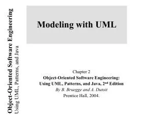
Learn about Project Scheduling in project management, including PERT Diagrams and Critical Path Method (CPM). Explore project phases, objectives, and techniques such as dummy activities. Understand how to allocate resources efficiently.

E N D
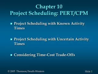
Lecture 4 – PERT Diagrams & CPM Maria Petridou Project Scheduling Project Scheduling Objectives Phases of Project Scheduling PERT Diagrams & Dummy Activities CPM – Critical Path Method
Project Scheduling • It is part of project management within the Planningphase of the Systems Development Life Cycle. • Project Scheduling: Allocate resources to execute all activities in the project. • Project: Set of activities or tasks with a clear beginningand endingpoints. The amount of available resources (time, personnel and budget) to carry out the activities is usually limited. Maria Petridou
Project Scheduling • Objectives: • Establish beginning, ending and duration of each activity in the project. • Calculate overall completion time of the project given the amount of usually limited resources. • Determine the critical path and its duration. • Determine the slack time for all non-critical activities and the whole project. • Guide the allocation of resources other than time such as staff and budget. Maria Petridou
Project Scheduling • Phases: • Define activities or tasks according to the project objectives. • A task is an individual unit of work with a clear beginning and a clear end. • Identify precedence relationships or dependencies • Estimate time required to complete each task. • Draw an activity-on-arrow PERT diagram inserting dummy activities if required. • Apply CPM to calculate earliest and lateststarting times, earliest and latestcompletion times, slack times, critical path etc. • Construct a GANTT chart. • Reallocate resources and resolve if necessary. • Continuously monitor/revise the time estimates along the project duration. Maria Petridou
PERT Diagrams • Program Evaluation and Review Technique • It is a network model that allows for randomness in activity completion times. • Tool used to control the length of projects. • PERT was developed in the late 1950’s for the US Navy’s Polaris Project. • First used as a management tool for military projects • Adapted as an educational tool for business managers • It has the potential to reduce both the time and cost required to complete a project. Maria Petridou
1 2 3 5 4 6 PERT Diagrams D B F A C Maria Petridou E Single start node Single finish node
PERT Diagrams • Activity-on-node diagrams: • Maybe more than one single start and end node • Nodes represent activities • Arrows indicate precedence • Activity-on-arrow diagrams: • One single start and one single end node • Arrows represent activities • Nodes indicate beginning/end of activities Maria Petridou
PERT Diagrams Activity-on-node Maria Petridou Activity-on-arrow
2 3 PERT Diagrams • Some basic rules for Activity –on-arrow: • Tasks are represented as arrows • Nodes represent the start and finish points of tasks • There is only one overall start node • There is only one overall finish node • Two tasks cannot share the same start and end node. B Maria Petridou D A C Tasks B & C share the same start and end node
Dummy Activities • Sometimes it is necessary to insert dummy activities (duration zero) in order to maintain the clarity of the diagram and the precedence relationships between activities. • In activity-on-arrow PERT diagrams, each activity must be uniquely identifiable by its start and end nodes. • However, sometimes multiple tasks have the same predecessors and successors. Maria Petridou
1 2 3 4 Dummy Activities Case One • A task should be uniquely identifiable from its start node and finish node • This means that two or more tasks cannot share the same start and finish nodes B Maria Petridou D A Task D has immediate predecessors of B and C C Tasks B and C have the same start and finish nodes
1 2 3 5 4 Dummy Activities • Inserting a dummy activity can ensure that multiple tasks have different successors. A B D C Maria Petridou A new node is inserted to give C a different finish node to B A dummy task is inserted to preserve the immediate predecessors of D
Dummy Activities Case Two • A task should be uniquely identifiable from its start node and finish node • This also means that a task cannot have more than one start node and one finish node • In other words… two different arrows cannot represent the same task. Maria Petridou
Dummy Activities Possible Solution One • One option would be to insert activity E as shown below, but this changes the precedence of E and provokes that D and E share both start and end nodes. Ending node of task B and C, but task C has a precedence ONLY task C Maria Petridou Task D and E have same start and end nodes
Dummy Activities Possible Solution Two • Another option would be to insert activity E as shown below, but this provokes C to have two different end nodes. Maria Petridou Two ending nodes for Task C
Dummy Activities Correct Solution! • The solution is to insert a dummy task so that the precedence of E is preserved and activity C remains uniquely identifiable. Maria Petridou
CPM – Critical Path Method • It is determined by adding the times for the activities in each sequence. • CPM determines the total calendar time required for the project. • If activities outside the critical path speed up or slow down (within limits), the total project time does not change. • The amount of time that a non-critical activity can be delayed without delaying the project is called slack-time. Maria Petridou
CPM – Critical Path Method • ET – Earliest node time for given activity duration and precedence relationships • LT – Latest node time assuming no delays • ES – Activity earliest start time • LS – Activity latest start time • EF – Activity earliest finishing time • LF – Activity latest finishing time • Slack Time – Maximum activity delay time Maria Petridou
CPM – Critical Path Method Step 1. Calculate ET for each node. For each node i for which predecessors j are labelled with ET(j), ET(i) is given by: ET(i)= maxj [ET(j)+ t(j,i)] where t(j,i) is the duration of task between nodes (j,i). Step 2. Calculate LT for each node. For each node i for which successors j are labelled with LT(j), LT(i) is given by: LT(i)= minj [LT(j) – t(i,j)] where t(j,i) is the duration of task between nodes (i,j). Maria Petridou
2 1 3 5 4 CPM – Critical Path Method A ( 3 ) D ( 5 ) Maria Petridou B ( 4 ) E ( 2 ) C ( 7 )
2 1 3 5 4 CPM – Critical Path Method A ( 3 ) D ( 5 ) 0 Maria Petridou B ( 4 ) E ( 2 ) C ( 7 )
2 1 3 5 4 CPM – Critical Path Method 3 A ( 3 ) D ( 5 ) 0 Maria Petridou B ( 4 ) E ( 2 ) 4 C ( 7 )
2 1 3 5 4 CPM – Critical Path Method 3 A ( 3 ) D ( 5 ) 0 Maria Petridou B ( 4 ) E ( 2 ) 4 11 C ( 7 )
CPM – Critical Path Method 3 2 1 5 4 3 13 A ( 3 ) D ( 5 ) 0 B ( 4 ) E ( 2 ) 4 11 C ( 7 ) 24 Software Project Management Maria Petridou
CPM – Critical Path Method 2 1 3 5 4 3 13 8 A ( 3 ) D ( 5 ) 0 B ( 4 ) E ( 2 ) 4 11 C ( 7 ) 25 Software Project Management Maria Petridou
CPM – Critical Path Method 2 1 3 5 4 3 13 max 8 A ( 3 ) D ( 5 ) 0 B ( 4 ) E ( 2 ) 4 11 C ( 7 ) 26 Software Project Management Maria Petridou
2 1 3 5 4 CPM – Critical Path Method 3 A ( 3 ) D ( 5 ) 0 13 Maria Petridou B ( 4 ) E ( 2 ) 4 11 C ( 7 )
2 1 3 5 4 CPM – Critical Path Method 3 A ( 3 ) D ( 5 ) 0 13 13 Maria Petridou B ( 4 ) E ( 2 ) 4 11 C ( 7 )
2 1 3 5 4 CPM – Critical Path Method 3 A ( 3 ) D ( 5 ) 0 13 13 Maria Petridou B ( 4 ) E ( 2 ) 4 11 11 C ( 7 )
2 1 3 5 4 CPM – Critical Path Method 3 8 A ( 3 ) D ( 5 ) 0 13 13 Maria Petridou B ( 4 ) E ( 2 ) 4 11 11 C ( 7 )
2 1 3 5 4 CPM – Critical Path Method 3 8 A ( 3 ) D ( 5 ) 0 13 13 Maria Petridou B ( 4 ) E ( 2 ) 4 4 11 11 C ( 7 )
CPM – Critical Path Method 2 1 3 5 4 3 8 5 A ( 3 ) D ( 5 ) 0 13 13 B ( 4 ) E ( 2 ) 4 4 11 11 C ( 7 ) 32 Software Project Management Maria Petridou
CPM – Critical Path Method 2 1 3 5 4 3 8 5 0 A ( 3 ) D ( 5 ) 0 13 13 B ( 4 ) E ( 2 ) 4 4 11 11 C ( 7 ) 33 Software Project Management Maria Petridou
CPM – Critical Path Method 2 1 3 5 4 3 8 5 min 0 A ( 3 ) D ( 5 ) 0 13 13 B ( 4 ) E ( 2 ) 4 4 11 11 C ( 7 ) 34 Software Project Management Maria Petridou
2 1 3 5 4 CPM – Critical Path Method 3 8 A ( 3 ) D ( 5 ) 0 0 13 13 Maria Petridou B ( 4 ) E ( 2 ) 4 4 11 11 C ( 7 )
CPM – Critical Path Method • An activity with zero slack time is a critical activity and cannot be delayed without causing a delay in the whole project. Maria Petridou
CPM – Critical Path Method Step 3. Calculate processing times for each activity. For each activity X with start node i and end node j: ES(X) = ET(i) EF(X) = ES(X) + t(X) LF(X) = LT(j) LS(X) = LF(X) – t(X) Slack Time (X) = LS(X) – ES(X) = LF(X) – EF(X) Where t(X) is the duration of activity X. An activity with zero slack time is a critical activity and cannot be delayed without causing a delay in the whole project. Maria Petridou
CPM – Critical Path Method Step 3. Calculate processing times for each activity. Maria Petridou Reading: (Kendall&Kendall, chapter 3), (Dennis &Wixom, chapter 3)
2 1 3 5 4 CPM – Critical Path Method 3 8 A ( 3 ) D ( 5 ) 0 0 13 13 Maria Petridou B ( 4 ) E ( 2 ) 4 4 11 11 C ( 7 )