Download
1 / 23
350 likes | 816 Views
seminar on Anti Locking Brakes DEPARTMENT OF MECHANICAL ENGINEERING SHANTHI CHARITABLE TRUST INSTITUTIONS OF TECHNOLOGY By V SANTOSH Reg no : 1SC08ME415 Under the guidance of Mr. Lecturer in mechanical department 2010-2011. Topics. Introduction to ABS History Modern system

E N D
seminar on Anti Locking Brakes DEPARTMENT OF MECHANICAL ENGINEERINGSHANTHI CHARITABLE TRUST INSTITUTIONS OF TECHNOLOGY By V SANTOSH Reg no:1SC08ME415 Under the guidance of Mr. Lecturer in mechanical department 2010-2011
Topics • Introduction to ABS • History • Modern system • Components of ABS • How they work together • Brake types • Disadvantage& advantage • With and with out ABS • Research Papers
INTRODUCTION • The anti-lock breaking is safety system that allows the wheel on a motor vehicle to continues interacting with the road surface as directing by driver steering input while braking. Prevent the wheel from locking up (that is ceasing rotation) and therefore avoiding skidding. • An ABS generally offers improved vehicle control and decreases stopping distances on dry and slippery surfaces for many drivers • Since initial widespread use in production cars, anti-lock braking systems have evolved considerably. Recent versions not only prevent wheel lock under braking, but also electronically control the front-to-rear brake bias. This function, depending on its specific capabilities and implementation, is known as electronic brake distribution.
HISTORY • The ABS was first developed for aircraft use in 1929 by the French automobile and aircraft pioneer, • 1950 Dunlop's MAXARET introduced a system and still in use on some aircraft models • In 1958, a Royal Enfield Super Meteor motorcycle was used to test the MAXARET anti-lock brake, The experiments demonstrated that anti-lock brakes can be of great value to motorcycles. • A fully system saw limited automobile use in the 1960s in the Ferguson p99 racing car, but the system proved expensive and unreliable in automobile use.
Modern systems • BENDIX corporation, introduced a computerized, three-channel, four-sensor all-wheel ABS called "Sure Brake" for its 1971. • General Motors introduced the "Track master" rear-wheel only ABS as an option on their Rear-wheel drive Cadillac models. • In 1988, BMW introduced the first motorcycle with an electronic-hydraulic ABS: the BMW K100 • In 2007, Suzuki launched its GSF1200SA (Bandit) with an ABS • Harley-Davidson began offering ABS as an option for police bikes. In 2008
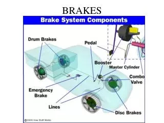
Components of ABS Master Cylinder Assembly Pressure Valve Speed Sensor Dump/Vent Valve ECU Anti Lock Anti-Lock Brake Module 12 V FIGURE-1 components of ABS
Speed sensors The anti-lock braking system needs some way of knowing when a wheel is about to lock up. The speed sensors, which are located at each wheel, or in some cases in the differential, provide this information FIGURE-2 speed sensor
Valves There is a valve in the brake line of each brake controlled by the ABS. On some systems, the valve has three positions: • In position one, the valve is open; pressure from the master cylinder is passed right through to the brake. • In position two, the valve blocks the line, isolating that brake from the master cylinder. This prevents the pressure from rising further should the driver push the brake pedal harder. • In position three, the valve releases some of the pressure from the brake. FIGURE-3 valves
Pump& accumulator Since the valve is able to release pressure from the brakes, there has to be some way to put that pressure back. That is what the pump does; when a valve reduces the pressure in a line, the pump is there to get the pressure back up. The fluid pressure that is generated by the pump is stored in the "accumulator." FIGURE-4 pump& accumulator
Controller The controller is an ECU type unit in the car which receives information from each individual wheel speed sensor, in turn if a wheel loses traction the signal is sent to the controller, the controller will then limit the brake force and activate the ABS modulator which actuates the braking valves on and off. FIGURE-5 controller
How They Work Together Each of these pieces of equipment have important duties in the case of a slide. The controller constantly monitors the speed sensors. If the speed sensors sense a deceleration that seems out of place, it puts the valves into action. The natural reaction for a driver when the car starts sliding is to slam on the brake. However, for the car to stop as quickly and safely as possible, the car and wheels must stop at roughly the same speed. FIGURE-6 operation
How They Work Together If the brakes reacted the same way the driver did, the wheel would stop their movement before the car, causing the car to slide out of control. The anti-lock brake system senses this and forces pressure out of the brakes by activating the valves. The controller then balances the brake pressure during the slide by releasing pressure from the brake system with the valve, and increasing the pressure with the pump. It does this until the car and the wheels are stopping at the same speed FIGURE-7 operation
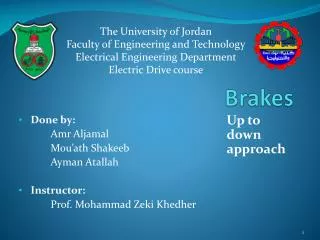
Brake types Anti-lock braking systems use different schemes depending on the type of brakes in use. They can be differentiated by the number of channels: that is, how many valves that are individually controlled and the number of speed sensors • 1 Channel • 3 Channel • 4 Channel
Brake types for ABS One channel • 1 channel ABS system controls the rear wheel together. • 1 channel system only has 1 speed sensor and control valve assembly • This system is commonly found on pickup trucks with rear-wheel ABS
Brake types for ABS Three channel • A three (3) channel ABS system control the rear wheel together and the front independently • Three channel ABS system have 3 speed sensor and one (1) control module • This scheme, commonly found on pickup trucks with four-wheel ABS
Brake types for ABS Four channel • is the best scheme. There is a speed sensor on all four wheels and a separate valve for all four wheels. With this setup, the controller monitors each wheel individually to make sure it is achieving maximum braking force.
Advantages of ABS • Good accuracy of working. • Safety system. • Preventing the wheel from locking and slippery surface. • ABS can apply to all kind of automobile and air craft. • Easy in operation.
Disadvantages • Increased braking distances under some limited circumstances (snow, gravel, "soft" surfaces), • Creation of a "false sense of security" among drivers who do not understand the operation, and limitations of ABS. • The anti-lock brakes are more sensitive on the damper condition. the influence of the worn components on the performance of the vehicle with anti-lock brakes is more significant than without anti-lock brakes, the stopping distance with defective shocks is by meters longer for the presented simulation scenario
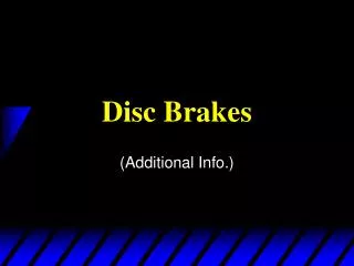
comparing of ABS FIGURE-8 with & with out ABS
Bibliography • Royal Automobile Club of Victoria, Effectiveness of ABS and Vehicle Stability Control Systems,, April 2004. • E.SCHWALLER, Total automotive technology, 4th edition April 27, 2004. P386. • JACK ERJAVEC, automotive technology, a system approach, 5th edition. 2008. • www.digg.com • www.howstuffworks.com
Bibliography Research Papers Base OnABS` • CHINMAYA B. PATIL and Raul G.LONGORIA,DEPT. of Mechanical Engineering, University of Texas at Austin, Control Prototyping for an Anti-Lock Braking Control System on a Scaled Vehicle, Proceedings of the 42nd IEEE Conference on Decision and Control Maui, Hawaii USA, December 2003 • SUDEENDRA KUMAR K, LESLIN VERGHESE, K. K. MAHAPATRA Department of Electronics Engineering, National Institute of Technology, Rourkela, India, Fuzzy Logic based Integrated Control of Anti-lock Brake System and Collision Avoidance System using CAN for Electric Vehicles • DINESH CHAWDE, Don Bosco Institute of Technology Department of Mechanical Engineering ,Mumbai , IMDAD A. RIZVI Department of Electronics and Telecommunication Engineering ,Don Bosco Institute of Technology ,Mumbai. Simulation Of Antilock Braking System,
Summary of research papers • Simulation Of Antilock Braking System- This paper develops the anti-lock braking control system integrated with active suspensions applied to a two wheeler. In emergency, although the braking distance can be reduced by the control torque, the braking time and distance can be further improved if the normal force generated from active suspension systems is considered simultaneously. • Fuzzy Logic based Integrated Control of Anti-lock Brake System and Collision Avoidance System using CAN for Electric Vehicles-This paper investigates the integrated control of Antilock Brake System (ABS) and Collision Avoidance System(CAS) in electric vehicle. Fuzzy logic techniques are applied for integral control of two subsystems. Control algorithm is implemented and tested in a prototype electric vehicle in laboratory environment using free scale HCS12 microcontroller. • Control Prototyping for an Anti-Lock Braking Control System on a Scaled Vehicle- This paper describes the design, simulation, implementation , and testing of wheel slip regulation in anti-lock brake systems on a one-fifth scaled vehicle. A sliding mode control design is presented, and simulation and test results demonstrate acceptable controller performance. Of note to control design is the use of a cascaded control scheme to simplify the wheel slip regulation problem, with the brake torque output of the vehicle controller