Download
1 / 38
380 likes | 514 Views
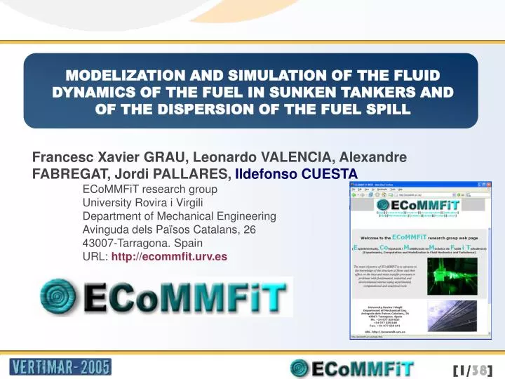
MODELIZATION AND SIMULATION OF THE FLUID DYNAMICS OF THE FUEL IN SUNKEN TANKERS AND OF THE DISPERSION OF THE FUEL SPILL. Francesc Xavier GRAU, Leonardo VALENCIA, Alexandre FABREGAT, Jordi PALLARES, Ildefonso CUESTA ECoMMFiT research group

E N D
MODELIZATION AND SIMULATION OF THE FLUID DYNAMICS OF THE FUEL IN SUNKEN TANKERS AND OF THE DISPERSION OF THE FUEL SPILL • Francesc Xavier GRAU, Leonardo VALENCIA, Alexandre FABREGAT, Jordi PALLARES, Ildefonso CUESTA • ECoMMFiT research group • University Rovira i VirgiliDepartment of Mechanical Engineering • Avinguda dels Països Catalans, 2643007-Tarragona. SpainURL: http://ecommfit.urv.es
OUTLINE • Introduction • Simulation of the fluid dynamics of the fuel in sunken tankers • Macroscopic model • Numerical simulation • Conclusions • Simulation of the fluid dynamics of fuel spills • Current work
INTRODUCTION • This presentation describes the main results obtained by the Fluid Mechanics Group of Tarragona ECoMMFiT within the project VEM2003-2004:"Modelization and simu-lation of the fluid dynamics of fuel within a sunken tanker and the subsequent oil slick“ • This project covers the development of CFD codes for the simulation of both flow/heat transfer processes: • of the oil in a sunken tanker and • the dispersion of oil spills.
INTRODUCTION • The research group developed two domestic codes for the simulation of : • fluid flow and heat/mass transfer 3DINAMICS • for the simulation of oil spills SIMOIL • These codes needed specific improvements and optimization of the numerical methods, as well as the extension of their simulation capabilities through the implementation of different models
Physical overview SIMULATION OF THE FLUID DYNAMICS OF THE FUEL IN SUNKEN TANKERS Central tank H=19 m Lc=15.2 m (only half is shown) At t=0... Lateral tank H=19 m Ll=9.6 m 104< Pr < 8 106 O(RaH) = 1013 g Unstable density stratification Highly unsteady flow Natural convection vertical boundary-layer Lc/2=7.6 m Stable density stratification
y x SIMULATION OF THE FLUID DYNAMICS OF THE FUEL IN SUNKEN TANKERS The macroscopic model • Hypothesis • The core of the tanks are perfectly mixed (Tl and Tc) • Correlations for natural convection on vertical and horizontal flat plates are used • Unsteady conduction heat transfer through the bottom walls ql t qc t Tl Tt Tc ql w ql e qc w ql b qc b
y x SIMULATION OF THE FLUID DYNAMICS OF THE FUEL IN SUNKEN TANKERS The macroscopic model • Energy balance in the lateral tank Lateral tank Central tank Top wall Bottom wall ql t qc t West wall Tt East wall Tl Tc • Energy balance in the central tank ql w ql e qc w Top wall Bottom wall West & east walls ql b qc b • Energy balance on the mid-wall
SIMULATION OF THE FLUID DYNAMICS OF THE FUEL IN SUNKEN TANKERS The macroscopic model Time evolution of the volume-averaged temperatures
SIMULATION OF THE FLUID DYNAMICS OF THE FUEL IN SUNKEN TANKERS Numerical Simulation Mathematical model • Hypothesis: 2D model, Boussinesq fluid except for the • temperature-dependent viscosity • Continuity • Momentum • Thermal energy
SIMULATION OF THE FLUID DYNAMICS OF THE FUEL IN SUNKEN TANKERS Numerical Simulation Mathematical model • Boundary conditions • No slip condition at the isothermal walls: ui=0, Tw=2.6ºC • Symmetry condition: (T/x)x=17.2m=0, (v/x)x=17.2m=0, ux=17.2m=0 • Initial conditions • T(x,y)=50ºC • ui=0
SIMULATION OF THE FLUID DYNAMICS OF THE FUEL IN SUNKEN TANKERS Numerical Simulation Mathematical model • Computational code: 3DINAMICS • Finite volume • 2nd order accuracy • QUICK discretization for the convective fluxes • Centered scheme for the diffusive fluxes • ADI method for time-integration • Coupling V-P: conjugate gradient method for the • iterative solution of the Poisson • equation
SIMULATION OF THE FLUID DYNAMICS OF THE FUEL IN SUNKEN TANKERS Numerical Simulation Mathematical model • Numerical method: 3DINAMICS • Tested successfully in the Validation Exercise • “Natural convection in an air filled cubical cavity with different inclinations” • CHT’01 Advances in Computational Heat Transfer II. May 2001. Palm Cove. Queensland. Australia 0º 90º Heated from the side Heated from below 104 Ra 108
SIMULATION OF THE FLUID DYNAMICS OF THE FUEL IN SUNKEN TANKERS Numerical Simulation • Numerical grids • Grid spacing Horizontal x-direction Nx=81, Ny=64 Nx=141, Ny=146 Vertical y-direction
SIMULATION OF THE FLUID DYNAMICS OF THE FUEL IN SUNKEN TANKERS Numerical Simulation • Results Results Time evolution of the volume-averaged temperatures
SIMULATION OF THE FLUID DYNAMICS OF THE FUEL IN SUNKEN TANKERS Numerical Simulation • Results Fine grid: 5 days only half of the vectors are shown in each direction
SIMULATION OF THE FLUID DYNAMICS OF THE FUEL IN SUNKEN TANKERS Numerical Simulation • Results Coarse grid: 42 days
CONCLUSIONS SIMULATION OF THE FLUID DYNAMICS OF THE FUEL IN SUNKEN TANKERS • The heat transfer process is governed by the interaction between the natural convection vertical boundary-layers along the lateral walls and the unstable stratification at the top walls • The macroscopic model gives reasonable time-evolution of the volume-averaged temperatures when temperature-dependence viscosity corrections are introduced in the conventional correlations
CONCLUSIONS SIMULATION OF THE FLUID DYNAMICS OF THE FUEL IN SUNKEN TANKERS • The high Prandtl number and the strong temperature-dependent viscosity require grid spacings of the order of millimeters near the walls • Maximum differences between predictions of the macroscopic model and the fine-grid numerical simulation are about 10% (t<5 days) • According to the macroscopic estimation after 500 days the temperature of the fuel is about 3ºC in both tanks
SIMOIL SIMULATION OF THE FLUID DYNAMICS OF FUEL SPILLS SIMOIL: computational code for the numerical simulation of the evolution of oil spills
SIMULATION OF THE FLUID DYNAMICS OF FUEL SPILLS Physical properties of oil • Oil is a complex mixture of many chemical compounds. • Composition of crude oil may differ depending of the zone of the extraction • Following the main components: • Hydrocarbons • Asphalts • Paraffins
SIMULATION OF THE FLUID DYNAMICS OF FUEL SPILLS Physical properties of oil DEGRADATION OF AN OIL SPILL • Spreading • Advection • Evaporation • Dispersion • Dissolution • Emulsification • Photo-oxidation • Sedimentation • Biodegradation
spreading SIMULATION OF THE FLUID DYNAMICS OF FUEL SPILLS Oil spill increases surface extension • gravity • inertia • Friction, viscosity • Surface tension
SIMULATION OF THE FLUID DYNAMICS OF FUEL SPILLS Mathematical model • In this work, a constant oil velocity profile has been assumed in the vertical direction, and the problem has been reduced to a two-dimensional one, with the thickness of the slick as the unique unknown. • All the fluids involved, air, sea water and crude oil, have been assumed to be newtonian and nonmiscible, with constant physical properties. • While spreading is dominated by gravity and viscous forces: in a gravity-viscosity dominated flow regime, the displacement of the oil slick is mainly due to the combined effect of wind and sea currents.
SIMULATION OF THE FLUID DYNAMICS OF FUEL SPILLS Mathematical model ADVECTION • A global convection velocity is calculated at each computational point and time step by adding to the actual sea motion the local induced sea current. • This induced velocity is assumed to be produced by known permanent currents and/or tidal flows, in which case the period and amplitude of tides are taken into account.
SIMULATION OF THE FLUID DYNAMICS OF FUEL SPILLS Mathematical model EVAPORATION • The evaporation process can produce losses up to 60% of the original spill. • The model developed by Mackay et al. (1980) has been adopted in this work. • This model is based on the concept of evaporative exposure as a function of elapsed time, oil slick surface and a mass transfer coefficient, which varies with wind velocity Kh = 0•00l5 W0.78
SIMULATION OF THE FLUID DYNAMICS OF FUEL SPILLS Mathematical model • A single governing equation for the evolution of the oil thickness hin isothermic systems can be obtained by combining the continuity and the momentum conservation equations. • Under a gravity-viscosity regime the vectorial form of this equation is
SIMULATION OF THE FLUID DYNAMICS OF FUEL SPILLS Mathematical model • The governing equation has been solved in a two-dimensional domain corresponding to the marine environment where the oil is spilled. • The discrete computational domain has been spanned by a generalized grid coordinate system, e, h
Computational grid Physical domain SIMULATION OF THE FLUID DYNAMICS OF FUEL SPILLS Mathematical model
SIMULATION OF THE FLUID DYNAMICS OF FUEL SPILLS Mathematical model DISCRETIZATION • The original equation is shown in generalized coordinates (e,h)
SIMULATION OF THE FLUID DYNAMICS OF FUEL SPILLS Mathematical model DISCRETIZATION • Previously equation has been discretized by means of a finite difference scheme which is first-order accurate (upwind) for the convective terms and second-order accurate (centred) for the diffusion-like terms. • At each time step, the set of resulting algebraic expressions was solved by using an alternating direction implicit (ADI) method to ensure second-order accuracy for the time derivative approximation.
SIMULATION OF THE FLUID DYNAMICS OF FUEL SPILLS Mathematical model INITIAL AND BOUNDARY CONDITIONS • Initial h values are needed to start a simulation. Therefore, the initial location, volume and extension of the oil slick have to be known. • The application of convective boundary conditions at the sea side allows the slick to cross the limits of the domain, i.e. to be convected away from the zone of calculation. • On the coast a convective-diffusive boundary condition has been developed so that oil can accumulate and disperse on the shoreline.
SIMULATION OF THE FLUID DYNAMICS OF FUEL SPILLS Mathematical model COMPUTATIONAL PROCEDURE • Generation of the computational domain. To this end the map of the area affected by the spill is digitized to obtain the boundary points comprising the open sea and land, and to generate the grid in generalized coordinates. • Secondly, the discrete space-time evolution of the oil slick, in terms of oil thickness, is calculated for any given input data. • The third step includes the graphical presentation of the results obtained.
SIMULATION OF THE FLUID DYNAMICS OF FUEL SPILLS Mathematical model COMPUTATIONAL PROCEDURE • The input information include the • definition of the domain of calculation-grid and land boundary definitions • the characteristics of the oil spill -initial location, density, amount of oil, continuous or discontinuous discharge, etc. • the environmental conditions - air and water temperature, wind speed and direction • the dynamic conditions of the sea, such as currents and tides • The graphic output displays the areas of equal oil thickness, by means of isolines and allows the direct evaluation of the position and area affected by the accident and eliminates the need for storing large sets of numerical data.
SIMULATION OF THE FLUID DYNAMICS OF FUEL SPILLS Mathematical model As a result a set of pictures for the time evolution of the slick is obtained
SIMULATION OF THE FLUID DYNAMICS OF FUEL SPILLS Mathematical model SIMOIL is implemented in a Linux cluster (beowulf) of 24 AMD opteron 248 processors (64 bits), with 3 Terabytes of Disk, linked with a Gigaethernet in a Linux environment
SIMULATION OF THE FLUID DYNAMICS OF FUEL SPILLS Mathematical model NUMERICAL EXEMPLE – INPUT DATA • Domain: Tarragona coast (35 km) • Wind: (5 m/s, -1 m/s) • Quantity spilled: A total 80000 m3 of crude oil continuously spilled in 24 h • Oil density: 870 kg/ m3 • Sea density: 1030 kg/ m3
SIMULATION OF THE FLUID DYNAMICS OF FUEL SPILLS Mathematical model
Current work • 3DINAMICS • The performance of the actual version code, which includes the paralelization and the multigrid technique, has been improved significantly. • Currently we are improving the speed-up of the parallel version • SIMOIL • More accurate results for spill spreading in coastal areas are obtained if the sea circulation is computed by a shallow water model which is currently being implemented • Implementation of better discretization schemes