Download
1 / 12
170 likes | 434 Views
Rocket Construction. Ou r Goal. Some questions: What do we hope to accomplish? What specification are required to accomplish this goal? How can we design to those specifications? What elements can we change with this rocket?. Parts of a Model Rocket. Body Tube Cylindrical cardboard tube

E N D
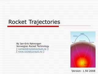
Rocket Construction UA Summer Engineering Program 2012
Our Goal • Some questions: • What do we hope to accomplish? • What specification are required to accomplish this goal? • How can we design to those specifications? • What elements can we change with this rocket? UA Summer Engineering Program 2012
Parts of a Model Rocket • Body Tube • Cylindrical cardboard tube • Engine Mount Assembly • Fixes engine to body tube • Launch Lugs • Small tubes (straws) attached to the body tube during launch • Nose Cone • Tapered to cut through air • Shock Cord • Connects body tube and nose cone UA Summer Engineering Program 2012
Parts of a Model Rocket, cont. • Recovery System • Consists of a parachute or streamers and lines to connect to the nose cone • Recovery Wadding • Prevents hot gas of the ejection from damaging the recovery system • Engine • Several slides to follow. • Fins • Several slides to follow. UA Summer Engineering Program 2012
Engine Engine casing contains: • Nozzle • Usually made of clay • Must withstand exhaust temperatures • Solid Propellant • Produces the hot gases • Igniter used for combustion • Used during powered flight • Delay Charge • Coasts to maximum altitude • Leaves a smoke trail • The length of the delay variesfrom 2 to 8 seconds • Ejection Charge • Produces a small explosion to expand hot gas through the engine mount, ejects the nose cone, and deploys the recovery system. UA Summer Engineering Program 2012
Types of Engines • Engine markings denote the thrust, impulse and delay time. • Thrust in Newtons • Sizes: • Color matters too: Also sized for CII, D, E Note: “T” denotes mini UA Summer Engineering Program 2012
Phases of Rocket • 1. Electrical Ignition and Launch • 2. Powered Ascent • Thrust • 3. Coast Phase • Tracking Smoke • 4. Peak Altitude • Apogee • 5. Ejection • 6. Recovery • 7. Touchdown http://www.youtube.com/watch?v=parRoxcG2rw&feature=player_embedded UA Summer Engineering Program 2012
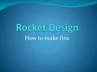
Fins • Fins give directional stability • Made of plastic, balsa wood or stiff cardboard. • Fixed • Fins should be attached in a symmetrical form of three, four or possibly more. • The four parts of a fin: • leading edge • trailing edge • root edge • tip UA Summer Engineering Program 2012
Design Considerations Design Elements: • Fin shapes • Rectangular • Elliptical • Straight-tapered • Swept-tapered • Fin Position • Inverting the fins • Where to place fin? • Number of Fins UA Summer Engineering Program 2012
Fin Position Ideas from Estes UA Summer Engineering Program 2012
What’s In the Viking Kit • 5 Fins • Cardstock • Shape: Swept-tapered • Body Tube • Length: 12.1 in.(30.7 cm) • Diameter: 0.74 in.(18.8 mm) • Molded Nose Cone • Streamer (Recovery) • Shock cord & Eyelet • Mount Assembly • Mount tube & Centering ring • Decals to decorate UA Summer Engineering Program 2012
References • Rocket Engine: • http://www.grc.nasa.gov/WWW/K-12/rocket/rktengine.html • http://www2.estesrockets.com/pdf/Estes_Model_Rocket_Engines.pdf • Rocket Parts: • http://www.grc.nasa.gov/WWW/K-12/rocket/rktparts.html • http://www2.estesrockets.com/pdf/ERL_T_9-12_3.pdf • http://www2.estesrockets.com/pdf/Fins%20and%20Nose%20Cones.pdf • http://www.estesrockets.com/rockets/kits/skill-1/001949-vikingtm • Rocket Flight: • http://www.grc.nasa.gov/WWW/K-12/rocket/rktflight.html UA Summer Engineering Program 2012