Download

1 / 46
600 likes | 1.13k Views
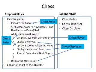
Interactive Automated Chess Set. Group 4 : Brett Rankin Paul Conboy Samantha Lickteig Stephen Bryant. Goals. To create a portable interactive chess board where gameplay will be fully automated. Each piece will be moved by a claw suspended above the board Person vs. Computer.

E N D
Interactive Automated Chess Set Group 4: Brett Rankin Paul Conboy Samantha Lickteig Stephen Bryant
Goals • To create a portable interactive chess board where gameplay will be fully automated. • Each piece will be moved by a claw suspended above the board • Person vs. Computer
Specifications • 90% chess piece movement accuracy • Total weight <100 lbs • 12”x12” playing grid
Features and Functions • LED lights will be used to light up the squares on the board • RGB, individual squares, communication with the user(s)
Features and Functions • Player modes: • 1.) Player vs. Computer • 2.) Player vs. Player • 3.) Computer vs. Computer
Mechanical • Three Motion Axis • One Gripper • Sliding A Frame Structure • Overhead Gantry • Stability and Consistent Repeatable Motion Control Needed
Gripper Claw • Gripper with Servo Goals • Purchase gripper and servo this was not a design item • One Micro Controller I/O output to command gripper open and closed • Pulse width command signal with a 20 ms period. The pulse on time will very to open and close the gripper.
Stepper Motors Two Motor Types both 12 Volt Bi-polar Stepper Motors. Torque Value for X & Y Axes rated at2.4Kg*cm Plan to Measure Force, Coefficient of Static and Dynamic Friction of our system
Motor Control • Design Goals • Single Modular Design for all Three Axes • Easy to bread board Avoid surface mount technology • Must be practical to install heat sink • Minimize micro controller I/O count • Based on proven reference design
Motor Control Schematic L297 L298
Stepper Resolution • Each step equals 1.8 degrees of angular displacement. • 200 steps per revolution • No feedback needed with stepper motors • X and Y axes have the same size gears and motors, so the scaling is the same • Z axis needs one half revolution of the large gear. 1REV = 1.978in 1Step ≈ .01in
Motion Control Circuits • X and Y Axes Over travel switches • E-Stop Switch • X,Y and Z Axes Home Sensors to provide the micro controller with a starting reference. • Gripper Open and or Closed sensor • Home and Gripper position sensors Digital Discrete Inputs
LED Grid • Purpose: • The grid of LEDs have a dual function, to add a lighting aesthetic to the board and visual cues for the player based on what is happening in the game. • The board itself does not have painted on black and white squares, like most chess boards, but rather it has the LEDs under the board turn on or off in a checkerboard pattern to make the distinction between squares. • The visual cues the LEDs give the player is to change color based on whether or not a piece is in danger of being taken, if one of the players are in check, or if a pawn has changed into another piece via the opponent’s side of the board.
LED Grid • Parts to use: • MAX7219 8X8 grid LED Driver • Plcc6 3 in 1 SMD LED
Hall Effect Sensor Grid • Purpose: • For the microcontroller to understand where the chess pieces are Hall Effect sensors are put under the board and grave yard. • The sensors will read whether or not the chess piece, which has a magnet embedded into it, is on particular squares.
Hall Effect Sensor Grid • Parts to use: • 4 to 16 Demultiplexer • 8 to 1 Multiplexer • Uni-polar linear Hall Effect sensors • 4 way Discrete Wire-to-Board surface mounted terminal blocks • 1k resistors • Schottky Diode
Hall Effect Sensor Grid • Specifications: • 4 to 16 Demultiplexer(HEF4514): VDD 5VDC • A0-A3, EL = 5VDC • O0-O15 5VDC • E(NOT), VSS= 0V • 8 to 1 Multiplexer(74HC151N) • 2.0 VCC,S2-S0 6.0 • 2.0 I0-I7 6.0 • E(NOT) = 0V • Uni-polar linear Hall Effect sensors(OH090U): • Vcc , Vout= 5VDC • Magnetic Hysteresis = 10 to 100 Gauss
Hall Effect Sensor Grid • Is an Optocoupler Needed?: • 4 to 16 Demultiplexer(HEF4514): • An optocoupler will be required to communicate with Microcontroller due to a voltage requirement of the demultiplexer being greater than 3.3VDC. • 8 to 1 Multiplexer(74HC151N) • Can directly communication with the Microcontroller due to 3.3VDC being within the multiplexer’s operating range.
Hall Effect Sensor Grid • Hall Effect Sensor Modular Design
User Interface • Displays messages • Prompts the user • Informs the user • Will have buttons for input selections Serial LCD Module 20x4 Blue with White Backlight for Arduino
Microcontroller Requirements • Must run an onboard minimalist chess engine • Large development community • Easy access to dev tools.
Microcontroller Specifications • 60 I/O pins • 4 hardware timers • 4 USART • 60 KB flash • 4 KB SRAM
Xmega128A1 • 8KB SRAM • 78 I/O pins • 8 UART for Serial • 8 Timers for PWM • 128KB Flash memory • AVRFreaks support community • Atmel Tutorials, Atmel software suite
Development Tools • A1Xplained Board • For testing individual components • Atmel Studio • USB gateway • Had to program using Atmel FLIP • No debugging
In System Programming • Ordered an AVR-ISP-MK2 • Program in system with PDI • Also has debugging capabilities
Main Module • Use only high level method calls • Describes high level gameplay process • Orchestrates interaction between I/O and Engine • Translates “moves” between chess engine and I/O module representations
Chess Module • Contains internal state of chess game • Accepts player moves and creates AI moves • Should use < 4 KB RAM • Micro-Max open source chess engine • Smallest chess engine in the world • Our goal was not to understand, but to interface.
I/O Module • Contains functions to interface with individual I/O devices • Exposes high level interface to main module
Motor Controller • All motor I/O functions grouped together • High level interface including “move piece”
Software Progress • Programed A1Xplained over USB • Created scaffolding for whole project • Ported and created interface to chess engine • Have claw servo working • We have single stepper motor to move • Created test suite for individual component testing • Got LCDs working with Arduino
Anticipated Problems • Motor controller • Currently runs with 1 of 4 wires disconnected • Changing I/O configurations as we go • Repeatability • Integration issues • Actually putting everything on the board
Test Plan • We have developed a written test plan • Acceptance Test Plan (ATP) where the Acceptance Test Results (ATR) are the final test results
Sponsors • Igus • Allied Electronics
Total Spent to Date $346.90