Download
1 / 68
940 likes | 2.2k Views
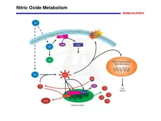
CHAPTER 6. OXIDE AND INTERFACE TRAPPED CHARGES, OXIDE THICKNESS. 6.1 INTRODUCTION. INTRODUCTION. Charges and their location for thermally oxidized silicon. . Interface trapped charge (Q it , N it , D it ) Fixed oxide charge (Q f , N f ) Oxide trapped charge (Q ot , N ot )

E N D
CHAPTER 6 OXIDE AND INTERFACE TRAPPED CHARGES, OXIDE THICKNESS
INTRODUCTION Charges and their location for thermally oxidized silicon. • Interface trapped charge (Qit, Nit, Dit) • Fixed oxide charge (Qf, Nf) • Oxide trapped charge (Qot, Not) • Mobile oxide charge (Qm, Nm) “Deal triangle” showing the reversibility of heat treatment effects on Qf.
Cross section and potential band diagram of an MOS capacitor.
Capacitance-Voltage Curves Qs=Qp+Qb+Qn+Qit
Capacitances of an MOS capacitor for various bias conditions as discussed in the text.
In order for the inversion charge to be able to respond, Jscr = qniW/τg≦ Jd = CdVg/dt W in μm, tox in nm, τg in μs
is the dimensionless semiconductor surface electric field. Us=φs/kT, UF=qφF/kT = ±1 is the intrinsic Debye length
Low-frequency (lf), high-frequency (hf), and deep-depletion (dd) normalized SiO2-Si capacitance-voltage curves of an MOS-C; (a) p-substrate NA= 1017 cm-3, (b) n-substrate ND = 1017 cm-3, tox= 10nm, T=300K.
(a) (b) • Effect of sweep direction on the hf MOS-C capacitance on an p-substrate, • entire C-VG curve, (b) enlarged portion of (a) showing the dc sweep • direction; f=1 MHz.
Flatband Voltage There is a built-in potential at epi-sub. junction normalized CFB
CFB/COX versus NA as a function of tox for the SiO2 -Si system at T=300K.
Schematic illustration of an MOS-C with finite gate doping density, showing gate depletion for positive gate voltage.
Low-frequency and high-frequency capacitance-voltage curves for various n+ polysilicon gate doping densities. The lowest Chf curve is for ND (gate) =1018 cm-3. Substrate NA =1016 cm-3, tox =10nm.
Capacitance Measurement for RG<<1 and (ωRC)2<<RG From the in-phase and out of phase component G and C can be determined. Simplified capacitance measuring circuit.
(a) (b) Block diagram of circuits to measure the current and charge of an MOS capacitor.
Low Frequency : Current-Voltage Low Frequency : Charge-Voltage CF is the feedback capacitance.
Ideal (line) and experimental (point) MOS-C curves. NA =5×1016 cm-3, tox=20nm, T=300K, CFB/Cox=0.77.
Gate-Semiconductor Work Function Difference Potential band diagram of a metal-oxide-semiconductor system at flatband.
Potential band diagram of (a) n+ polysilicon-p substrate, and (b) p+ polysilicon-n substrate at flatband.
Oxide Trapped Charge Flatband voltage of polysilicon-SiO2-Si MOS devices as a function of oxide thickness.
Work function difference as a function of doping density for polysilicon-SiO2 MOS devices.
Mobile Charge Drift time for Na, Li, K, and Cu for an oxide electric field of 106 V/cm and tox =100 nm.
C-VG curves illustrating the effect of mobile charge motion.
CIf and Chf measured at T=250OC. The mobile charge density is determined from the area between the two curves.
Low-Frequency (Quasi-static) Method • Semiconductor band diagram illustrating the effect of interface traps; (a) V=0, (b) V>0, (c) V<0. Electron-occupied interface traps are indicated by the small horizontal heavy lines and unoccupied traps by the light lines
(a) (c) Theoretical ideal (Dit=0) and Dit ≠0 (a) hf , (b) If and (c) experimental lf C-V curves. (b)
High- and low-frequency C-VG curves showing the offset △C/Cox due to interface traps.
Interface trapped charge density from the hf curve and the offset △C/Cox.
Conductance Method (a) MOS-C with interface trap time constant τit=RitCit , (b) simplified circuit of (a), (c) measured circuit, (d) including series rs resistance and tunnel conductance Gt.
Gp/ω versus ω for a single level, a continuum and experimental data. For all curves: Dit =1.9×109 cm-2 eV-1, τit=7×10⁻⁵s.
Interface trapped charge density versus energy from the quasi-static and conductance methods. (a) (111) n-Si, (b) (100) n-Si.
High-Frequency Methods Terman method: Gray-Brown method: The hf capacitance is measured as a function of temperature.
Charge Pumping Method Circuit diagram and energy bands for charge pumping measurement. The figures are explained in the text.
(c) (d) (e) (f)
Dit=7×109cm-2eV-1 MOSFET Qcp versus frequency
Trilevel charge pumping waveform and corresponding band diagrams.
(a) Icp as a function of tstep showing τe at the point where Icp begins to saturate. (b) insulator trap density versus insulator depth from the insulator/Si interface for Al2O3 and SiO2.