Download
1 / 98
1.07k likes | 1.64k Views
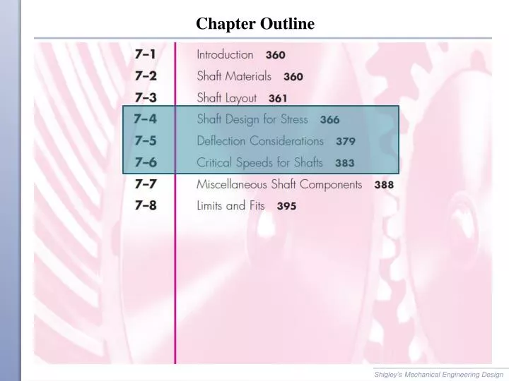
Chapter Outline Shaft Design for Stress Stresses are only evaluated at critical locations Critical locations are usually On the outer surface Where the bending moment is large Where the torque is present Where stress concentrations exist Shaft Stresses

E N D
Chapter Outline Shigley’s Mechanical Engineering Design
Shaft Design for Stress • Stresses are only evaluated at critical locations • Critical locations are usually • On the outer surface • Where the bending moment is large • Where the torque is present • Where stress concentrations exist Shigley’s Mechanical Engineering Design
Shaft Stresses • Standard stress equations can be customized for shafts for convenience • Axial loads are generally small and constant, so will be ignored in this section • Standard alternating and midrange stresses • Customized for round shafts Shigley’s Mechanical Engineering Design
Shaft Stresses • Combine stresses into von Mises stresses Shigley’s Mechanical Engineering Design
Shaft Stresses • Substitute von Mises stresses into failure criteria equation. For example, using modified Goodman line, • Solving for d is convenient for design purposes Shigley’s Mechanical Engineering Design
Shaft Stresses • Similar approach can be taken with any of the fatigue failure criteria • Equations are referred to by referencing both the Distortion Energy method of combining stresses and the fatigue failure locus name. For example, DE-Goodman, DE-Gerber, etc. • In analysis situation, can either use these customized equations for factor of safety, or can use standard approach from Ch. 6. • In design situation, customized equations for d are much more convenient. Shigley’s Mechanical Engineering Design
Shaft Stresses • DE-Gerber where Shigley’s Mechanical Engineering Design
Shaft Stresses • DE-ASME Elliptic • DE-Soderberg Shigley’s Mechanical Engineering Design
Shaft Stresses for Rotating Shaft • For rotating shaft with steady bending and torsion • Bending stress is completely reversed, since a stress element on the surface cycles from equal tension to compression during each rotation • Torsional stress is steady • Previous equations simplify with Mmand Ta equal to 0 Shigley’s Mechanical Engineering Design
Checking for Yielding in Shafts • Always necessary to consider static failure, even in fatigue situation • Soderberg criteria inherently guards against yielding • ASME-Elliptic criteria takes yielding into account, but is not entirely conservative • Gerber and modified Goodman criteria require specific check for yielding Shigley’s Mechanical Engineering Design
Checking for Yielding in Shafts • Use von Mises maximum stress to check for yielding, • Alternate simple check is to obtain conservative estimate of s'max by summing s'a and s'm Shigley’s Mechanical Engineering Design
Example 7-1 Shigley’s Mechanical Engineering Design
Example 7-1 Shigley’s Mechanical Engineering Design
Example 7-1 Shigley’s Mechanical Engineering Design
Example 7-1 Shigley’s Mechanical Engineering Design
Example 7-1 Shigley’s Mechanical Engineering Design
Estimating Stress Concentrations • Stress analysis for shafts is highly dependent on stress concentrations. • Stress concentrations depend on size specifications, which are not known the first time through a design process. • Standard shaft elements such as shoulders and keys have standard proportions, making it possible to estimate stress concentrations factors before determining actual sizes. Shigley’s Mechanical Engineering Design
Estimating Stress Concentrations Shigley’s Mechanical Engineering Design
Reducing Stress Concentration at Shoulder Fillet • Bearings often require relatively sharp fillet radius at shoulder • If such a shoulder is the location of the critical stress, some manufacturing techniques are available to reduce the stress concentration • Large radius undercut into shoulder • Large radius relief groove into back of shoulder • Large radius relief groove into small diameter of shaft Fig. 7-9 Shigley’s Mechanical Engineering Design
Example 7-2 Shigley’s Mechanical Engineering Design
Example 7-2 Fig. 7-10 Shigley’s Mechanical Engineering Design
Example 7-2 Shigley’s Mechanical Engineering Design
Example 7-2 Shigley’s Mechanical Engineering Design
Example 7-2 Shigley’s Mechanical Engineering Design
Example 7-2 Shigley’s Mechanical Engineering Design
Example 7-2 Shigley’s Mechanical Engineering Design
Example 7-2 Shigley’s Mechanical Engineering Design
Example 7-2 Shigley’s Mechanical Engineering Design
Example 7-2 Shigley’s Mechanical Engineering Design
Example 7-2 Shigley’s Mechanical Engineering Design
Example 7-2 Shigley’s Mechanical Engineering Design
Example 7-2 Shigley’s Mechanical Engineering Design
Example 7-2 Shigley’s Mechanical Engineering Design
Deflection Considerations • Deflection analysis at a single point of interest requires complete geometry information for the entire shaft. • For this reason, a common approach is to size critical locations for stress, then fill in reasonable size estimates for other locations, then perform deflection analysis. • Deflection of the shaft, both linear and angular, should be checked at gears and bearings. Shigley’s Mechanical Engineering Design
Deflection Considerations • Allowable deflections at components will depend on the component manufacturer’s specifications. • Typical ranges are given in Table 7–2 Shigley’s Mechanical Engineering Design
Deflection Considerations • Deflection analysis is straightforward, but lengthy and tedious to carry out manually. • Each point of interest requires entirely new deflection analysis. • Consequently, shaft deflection analysis is almost always done with the assistance of software. • Options include specialized shaft software, general beam deflection software, and finite element analysis software. Shigley’s Mechanical Engineering Design
Example 7-3 Fig. 7-10 Shigley’s Mechanical Engineering Design
Example 7-3 Shigley’s Mechanical Engineering Design
Example 7-3 Fig. 7-11 Shigley’s Mechanical Engineering Design
Example 7-3 Shigley’s Mechanical Engineering Design
Example 7-3 Shigley’s Mechanical Engineering Design
Adjusting Diameters for Allowable Deflections • If any deflection is larger than allowed, since I is proportional to d4, a new diameter can be found from • Similarly, for slopes, • Determine the largest dnew/dold ratio, then multiply all diameters by this ratio. • The tight constraint will be just right, and the others will be loose. Shigley’s Mechanical Engineering Design
Example 7-4 Shigley’s Mechanical Engineering Design
Angular Deflection of Shafts • For stepped shaft with individual cylinder length li and torque Ti, the angular deflection can be estimated from • For constant torque throughout homogeneous material • Experimental evidence shows that these equations slightly underestimate the angular deflection. • Torsional stiffness of a stepped shaft is Shigley’s Mechanical Engineering Design
Critical Speeds for Shafts • A shaft with mass has a critical speed at which its deflections become unstable. • Components attached to the shaft have an even lower critical speed than the shaft. • Designers should ensure that the lowest critical speed is at least twice the operating speed. Shigley’s Mechanical Engineering Design
Critical Speeds for Shafts • For a simply supported shaft of uniform diameter, the first critical speed is • For an ensemble of attachments, Rayleigh’s method for lumped masses gives Shigley’s Mechanical Engineering Design
Critical Speeds for Shafts • Eq. (7–23) can be applied to the shaft itself by partitioning the shaft into segments. Fig. 7–12 Shigley’s Mechanical Engineering Design
Critical Speeds for Shafts • An influence coefficient is the transverse deflection at location I due to a unit load at location j. • From Table A–9–6 for a simply supported beam with a single unit load Fig. 7–13 Shigley’s Mechanical Engineering Design
Critical Speeds for Shafts • Taking for example a simply supported shaft with three loads, the deflections corresponding to the location of each load is • If the forces are due only to centrifugal force due to the shaft mass, • Rearranging, Shigley’s Mechanical Engineering Design
Critical Speeds for Shafts • Non-trivial solutions to this set of simultaneous equations will exist when its determinant equals zero. • Expanding the determinant, • Eq. (7–27) can be written in terms of its three roots as Shigley’s Mechanical Engineering Design