Download

1 / 32
360 likes | 816 Views
Deadlock and Livelock. Ingo Sander ingo@imit.kth.se. Deadlock. Deadlock can occur in an interconnection network, when a group of agents (usually packets) cannot make progress, because they are waiting on each other to release resource (buffers, channels)

E N D
Deadlock and Livelock Ingo Sander ingo@imit.kth.se
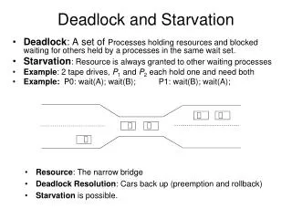
Deadlock • Deadlock can occur in an interconnection network, when a group of agents (usually packets) cannot make progress, because they are waiting on each other to release resource (buffers, channels) • If a sequence of waiting agents form a cycle the network is deadlocked IL2207 SoC Architectures
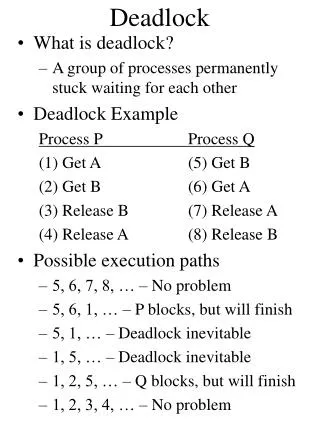
Deadlock Examle • Connection A holds channels u and v and wants to acquire channel w • Connection B holds channels w and x and wants to acquire channel u • Since neither connection A nor connection B will release their channels there is a deadlock in the network Circuit Switched Network IL2207 SoC Architectures
Deadlock • Deadlock paralyzes the network, which can have catastrophic consequences • Two possible solutions • Avoid deadlocks • Recover from deadlocks • Almost all networks today use deadlock avoidance IL2207 SoC Architectures
Livelock • In livelock packets continue to move through the network, but do not make progress to their destination • Lifelock has to be considered, if packets are allowed to take non-minimal routes through a network • It can be avoided by limiting the number of times a packet can be misrouted IL2207 SoC Architectures
Agents and Resources • Depending on the type of connections different agents and resources are involved IL2207 SoC Architectures
Wait-For and Hold-Relations • Agents and resources are related by wait-for and hold relations • Agent A • Holds resources u, v • Waits for resource w • Agent B • Holds resources w, x • Waits for resource w IL2207 SoC Architectures
Wait-For and Hold-Relations • If an agent holds a resource than the resource can be viewed as “waiting” for the agent to release it • Thus each hold relation induces a wait-for relation in the opposite direction holds A u waits for A u IL2207 SoC Architectures
Wait-For and Hold-Relations • Replacing the holds with wait for in the opposite direction, the lower figure is generated • The arrows in the figure reveal a cycle that shows that the configuration is deadlocked IL2207 SoC Architectures
Cycles mean Deadlock • Deadlock occurs, if • Agents hold and do not release a resource, while waiting for another • A cycle exists between waiting agents, such that there exists a set of agents A0, A1, …, An-1, where the agent Ai holds resource Ri while waiting for resource R(i+1 mod n) for i = 0, 1, …, n-1 IL2207 SoC Architectures
Resource Dependences • In case two resources Ri and Ri+1 are two edges apart in the wait-for graph, it is possible for an agent Ai holding resource Ri to wait indefinitely on resource Ri+1, if Ri+1 is never released. • Whenever it is possible for an agent holding Ri to wait on Ri+1, we say that a resource dependence exists from Ri to Ri+1, and denote it as Ri ≻Ri+1 IL2207 SoC Architectures
Resource Dependences • A cycle in the resource dependence graph indicates that it is possible for a deadlock to occur • A cycle in this graph is a necessary, but not sufficient condition for deadlock u ≻ ≻ x v ≻ ≻ w Resource Dependence Graph IL2207 SoC Architectures
Another example • Again the four node network is taken as example, but this time packet buffer flow with a single packet buffer per node is used • Agents are packets • Shared resources are now buffers B0 B1 B2 B3 Resource Dependence Graph IL2207 SoC Architectures
Another example • Again the four node network is taken as example, but this time packet buffer flow control with a single packet buffer per node is used • Agents are packets • Shared resources are now buffers • The resource dependence graph says that deadlock might occur B0 B1 B2 B3 Resource Dependence Graph IL2207 SoC Architectures
Another example Wait-for Graph • Once again, the resource dependence graph only shows the possibility for deadlock • The upper configuration is deadlocked • The lower one is not! Packet 3 can acquire buffer 0 P0 P1 P2 P3 B0 B1 B2 B3 Deadlock Configuration! P0 P1 P2 P3 B0 B1 B2 B3 Configuration not deadlocked IL2207 SoC Architectures
… and another one • Again the four node network is taken as example, but this time flit buffer flow control with two virtual channels per physical channel is used • Agents are packets • Shared resources are virtual channels • The resource dependence graph says that deadlock might occur Resource Dependence Graph IL2207 SoC Architectures
… and another one • The example shows a deadlocked configuration • Packet P0 holds virtual channel u0 and v0 and tries to acquire w0 • Packet P1 holds virtual channel w0 and x0 and tries to acquire u0 • Though there are free virtual channel resources there is a cycle in the network IL2207 SoC Architectures
Deadlock Avoidance • Deadlock can be avoided by eliminating cycles in the resource dependence graph • This can be done by imposing a partial order on the resources and then insisting on that agents take these resource in ascending order • Then there is no possibility for a cycle, since in any cycle at least one agent that hold a higher-number resource must wait on a lower-numbered resource, but this is not allowed by the ordering relation IL2207 SoC Architectures
Distance Classes • Resources are grouped into numbered classes and restrict allocation of resources of resources so that they only can be acquired in ascending order IL2207 SoC Architectures
Distance Classes Example • A packet at distance i from its source node needs to allocate a resource from class i • At each hop, the packet acquires a hop from the next higher class IL2207 SoC Architectures
Distance Classes Example • Using distance classes the resource dependence graph can look like this • There are no cycles => deadlock cannot occur! IL2207 SoC Architectures
Distance Classes • Distance classes provide a very general way to order resource in any topology • Distance Classes are very costly, since they require a number of buffers (or virtual channels) proportional to the diameter of the network • However, for some topologies the cost can be reduced significantly because of specific topology properties IL2207 SoC Architectures
Dateline Classes • For a ring the number of needed classes can be much reduced • Each node has only two buffers • Class “0” buffer: B0i • Class “1” buffer: B1i • Packets enter the ring in node B0i • When they cross the dateline, they are placed into buffer B1i until they reach their destination • Result is an acyclic graph => Deadlock cannot occur! IL2207 SoC Architectures
Restricted Physical Routes • Dividing the network into different classes allows to create a deadlock free network, but can be very costly to the large number of resources needed • An alternative is to restrict the routing function with the objective to generate a dependence graph that is acyclic IL2207 SoC Architectures
Dimension Order Routing • Dimension Order Routing guarantees deadlock-freedom in k-ary n-meshes • Within the first dimension (here x) a packet traveling in +x direction can only wait on a channel on the +x, +y, and -y direction • In the second dimension a packet traveling on the +y direction can only wait on a channel on the +y direction • These relations can be used to number the channels, so that every packet follows increasingly numbered channels IL2207 SoC Architectures
The Turn Model • A more general model for Mesh-networks is the “Turn Model” • The eight possible turns in a 2D-Mesh can be combined to create 2 abstract cycles • In order to avoid deadlock at least one turn must be removed for each cycle Counterclockwise Clockwise IL2207 SoC Architectures
Dimension Order Routing • Only the following turns are allowed (x-y routing) in dimension order routing (x-direction is routed first) Counterclockwise Clockwise IL2207 SoC Architectures
The Turn Model • Assume we remove the N-W turn in the counter-clockwise graph • In the clockwise direction either the S-W, N-E or E-S turn can be eliminated in order to yield a deadlock-free network (Turn W-N cannot be eliminated! Why?) Counterclockwise Clockwise West-First North-Last Negative-Last IL2207 SoC Architectures
Turn Model West First 1 • In the West-First model a packet has first to make all its west turns (1) • Packets shall be routed up (clockwise) or down (counterclockwise) before making a turn to the east (2) • Packet shall then be routed to the east (3) • Packets shall be routed down (clockwise) or up (counterclockwise) if needed (4) • This scheme shall be reflected by the numbering! 3 4 2 2 4 3 1 IL2207 SoC Architectures
Deadlock Recovery • Deadlock recovery needs less resources then deadlock avoidance • A deadlock must be first detected • A cycle in the “wait-for” graph indicates a deadlock • Detection is often done by means of timeout counters • … and then the deadlock must be resolved • Either packets or connections are removed from the network • Packets that are deadlocked can enter an “escape buffer” that is used to resolve the deadlock IL2207 SoC Architectures
Livelock • Can be caused by a non-minimal routing algorithm where a packet never reaches is destination due to misrouting • Can also be caused by dropping flow techniques where the same packet is always dropped IL2207 SoC Architectures
Livelock • There are two main techniques to avoid livelock: • Deterministic Avoidance • A state is added to a packet to ensure its progress • Misroute count or age of packet • Packet with higher age or misroute count wins arbitration • Probabilistic Avoidance • If it can be guaranteed that the probability of packet delivery approaches one for infinite time there is a guarantee to avoid livelock • Network can be considered livelock free, if there is a non-zero probability of a packet moving towards its destination (and the sum of these probabilities must approach one for infinite time) IL2207 SoC Architectures