Download

1 / 42
420 likes | 646 Views
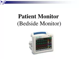
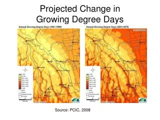
Growing Degree Day Monitor. Group 26 Anthony De Roo , John Habegger , Jay Zhaoyu Yao ECE 445 May 2, 2014. Introduction. Growing degree day monitor (GDDM) provides a cost effective solution to track crop maturation throughout the growing season

E N D
Growing Degree Day Monitor Group 26 Anthony De Roo, John Habegger, Jay Zhaoyu Yao ECE 445 May 2, 2014
Introduction Growing degree day monitor (GDDM) provides a cost effective solution to track crop maturation throughout the growing season Integrates temperature sensors, a microcontroller, flash memory, USB, and display in order to record cumulative growing degree days
Features Temperature collection and data computation Initiate degree day calculation when soil reaches germination temperature Temperature data logged during the course of season Displays instant degree day status Solar and battery powered USB interface
Case Dimensions Bud Industries. (4 February 2014). Tablet Enclosure, TB-32610-W [online] Available: http://www.budind.com/pdf/hb32610.pdf
System Overview • Hardware: • Power Module: Solar Panel, Switch FETs, Rechargeable Batteries, Voltage Regulator • User Interface: Display Driver, 7-Segment Displays, Push Button • Controller Module: Microcontroller (TI MSP430), Flash Memory • Sensor Module: Temperature Transducer Soil (Ground), Temperature Transducer Air (Ambient) • I/O Interface: USB Hardware
System Overview Software: • Power Module: Activate Solar Panels to Charge Batteries • User Interface: Display Driver, Status LED Illumination • Controller Module: Write and Read to the Flash Memory • Sensor Module: A/D Voltage to Temperature Conversion • I/O Interface: USB Data Transfer, Java GDDM Program
Power Module Solar Panels • Charge batteries during day • Provide up to 6V of voltage (6V in full sun, 5.3V in overcast) • Current provided at 50mA Batteries • Produce 4.8V to circuit to drive display, monitor LEDs, and sensor • 700mAH of capacity to last for several days Switch FETS • Signal from MSP430 delivers charge enable signal, connecting solar panels to battery • Monitored by 2:1 voltage divider across panels and batteries Voltage Regulator • Produce 3.3V of voltage up to 150mA • Power MSP430, display drivers, and flash memory
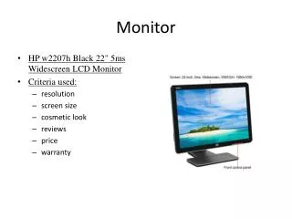
User Interface Display Driver • Each drive 2 7-segment displays • Segment current set by limiting resister Seven Segment Display • Displays growing degree day number Display Button • Interrupt high to low transition • Displays 7-segment display for 5 seconds Status LED • Blinking 15 second timer.
Control Module MSP430F5510IPT 4 A/D lines to monitor sensors and power voltage divider SPI to need to interface with flash chip General purpose I/O pins to drive display, enable charging, and indicate device status Real time clock (RTC) support Easy to program USB support
Control Module Flash Memory Must be able to write daily temperature records to the memory Needs to use Serial Peripheral Interface (SPI) communication Total storage of 512 kB across 8 sectors 256 B page size Can only write 1 to 0 unless on delete operation
Sensor Module 2 Temperature Sensors Ground and ambient air temperatures Ground temperature sensor purpose Frequency of readings Calibration Methods
I/O Interface Module USB Process • Initiation and communicate with GDDM • Enumeration with host computer GDDM Java Program • Send commands and receive data • Commands to interact with the GDDM
Verification and Testing Hardware requirements verified through multimeter using test points Software requirements verified through TI Code Composer using MSP430 FET tool
Commercial Market Manufacturing • PCB costs to roughly $10 a board • Case and stand costs at $15 • Economies of scale on components for $30 • Automated build process • Pick and place • Reflow • Automated testing with bed of nails and chip flashing Target Market • Individuals tracking growing conditions (farmers, gardeners, etc.) • 2.2 million farmers in the United States USDA. 2007 Census of Agriculture [online]. Available: http://www.agcensus.usda.gov/Publications/2007/Online_Highlights/Fact_Sheets/Demographics/demographics.pdf
Issues Encountered During Project Flash memory writing procedure Soldering difficulties due to initial reflow design Contamination created due to hardware debugging Implementation of software on MSP430
Future Hardware Development Wireless capability (Bluetooth for data transfer) Additional sensors to record other crop information Change several pinoutson the device to avoid fabrication issues Adjust ground temperature sensor’s molex connector Add thermal reliefs to all ground vias Develop formal procedure for adding parts to PCB
Future Software Development Allow the user to modify the requirements to start the device process for different climate regions Additional metrics measured and stored in memory Ability to easily update information stored in memory Improved user interface for the computer Additional user and debugging commands from the computer Separate user and factory software builds Implementation of lower power modes for microcontroller and flash memory IC Recovery of the GDDM from loss of power
Credits Professor Paul Carney Michelle Ansai Rishi Ratan ECE Machine Shop: Skee Aldrich ECE Part Shop: SkotWiedmann Advanced Circuits: Kyle Askew Texas Instruments
Power Module Schematic Solar Panel and Batteries
Power Module Schematic Voltage Regulator
User Interface Schematic Display Drivers
User Interface Schematic Monitor LED and Pushbutton
Reference Board Schematics Texas Instruments. MSP-EXP430F5529LP Schematics, BOM, and Software (Rev. B) [online]. Available: http://www.ti.com/lit/zip/slac623 Texas Instruments. MSP-TS430RGC64USB Development Board Schematics, Layout, and BOM (Rev. A) [online]. Available: http://www.ti.com/lit/zip/slac374
Prototype Flash Memory Chip and Display Drivers Interface with MSP430