Download

1 / 30
440 likes | 692 Views
Wave Relay: Multi-hop Wireless Ad hoc Network. Baruch Awerbuch, David Holmer, Herbert Rubens. {baruch dholmer herb}@cs.jhu.edu. Johns Hopkins University Department of Computer Science. www.cnds.jhu.edu/archipelago/. Goals: Design a system that…. Supports a large number of nodes thousands

E N D
Wave Relay:Multi-hop Wireless Ad hoc Network Baruch Awerbuch, David Holmer, Herbert Rubens {baruch dholmer herb}@cs.jhu.edu Johns Hopkins University Department of Computer Science www.cnds.jhu.edu/archipelago/
Goals: Design a system that… • Supports a large number of nodes • thousands • Moving at high speeds • greater then 40 mph • In an urban environment • High multi-path, rapidly fluctuating channels • Running real-time applications • Voice, video, interactive distributed applications • With or without help from fixed infrastructure • If its available use it to be more efficient
Wave Relay Test-bed • Over 50 Wave Relay Routers deployed across JHU Campus • Urban City Environment • Internet Access, Ad hoc Access Points, Voice over IP • Mobility testing from automobiles • System tested at Holcim Industrial Plant (Chicago, IL) • Complex propagation environment • Massive multi-path • Enabled real-time industrial process control • Currently Deployed Custom Applications • Military Distributed Battlefield Mapping • GPS based interactive map • Eventual reliability • Locality Specific Messaging System • GPS based messaging system • Messages targeted to any user at a specific location
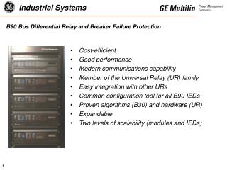
Pulse Protocol [Infocom’04, Milcom’04, WONS’05] Scalable ad hoc routing protocol Active path tracking Based on Tree Routing strategy Medium Time Metric [MONET,WONS’04] High Throughput Path Selection Increased Path Elasticity Efficient Multi-rate Operation Leader Election Algorithm Handles merge, partition, failure Embedded Linux Distribution Less then 8 MB storage requirement Linux Kernel Module 2.4 and 2.6 compatibility Operates at layer 2 Distributed virtual switch architecture provides seamless bridging Embedded Single Board Computer NS Geode SC1100 266 MHz Processor 64 Mb Ram onboard 2 mini-PCI interfaces 1 Compact flash interface Serial port 10/100 Ethernet Hardware Watchdog Power over Ethernet +7V to +18V DC Input Atheros 802.11g/b Wireless Card 400 mW (26 dBm) output power 16 MB Industrial Compact Flash Stores OS & Wave Relay software Garmin GPS 16 receiver Li-Ion Battery Pack ~20 hours continuous runtime Industrial NEMA 67 Enclosure 4 N-type antenna mounts 2 Ethernet Ports (6) protection against dust (7) water submersible Wave Relay Device Software Hardware
Existing Approaches Urban Channel Environment Receivers • Multi-path fading & shadowing • Rapidly changing channel conditions On-Demand Protocols (AODV, DSR) • On-demand protocols have no knowledge of channels conditions • A RREQ packet provides only a single sample of a complex distribution Destination Link State Protocols (OLSR, TBRPF) Source • Channel is continuously changing • Continuous flooding from every node in the network You can not accurately track channel with control packets!
The Pulse Protocol • Proactive Component • Tracks minimum amount of information to avoid flooding for route establishment and maintenance • Periodic flood operation (similar to Hello Protocol) • Rebuilds spanning tree • Estimates neighbors, density, SNR, loss rates, capabilities, number of radios, MTM metric • On-Demand Component • Route establishment • Using only UNICASTS! • Gratuitous mechanism • Neighbors promiscuously monitor packets • Metric tracked at the speed of data packets NOT control packets! • Path switches as metrics change • Local changes in connectivity only generate local traffic • Unlike BOTH on-demand and link state protocols
Initial Path: Tree Shortcut Tree Shortcut Path Shortest Path 3 Hops 2 Hops This is the initially selected path of the Pulse protocol.
Path Optimization: Gratuitous Reply Optimized Path Shortest Path 2 Hops 2 Hops Node sends gratuitous reply
Pulse Protocol Concepts • Aggregation – for scalability • Spanning tree represents a compressed view of the network topology • Pro-active component maintains the minimum amount of information to allow efficient route establishment • De-Aggregation – for efficiency • The routing metric is tracked at the speed of the data flow • Changes to the metric are only reported locally • Routes are continuously adjusted as the metrics change • High speed accurate route tracking is essentially an on-demand decompression of the topology • However, it occurs ONLY in areas of the network with active data flows • Result: a scalable routing structure which tracks paths at the speed of the data flow
Future Work • Security (NDSS 2005) • Wormholes, black-holes, flood rush, replay • Provide • Node authentication • End-to-end encryption • Broadcast/Routing Encryption • Efficient node addition/removal • Distributed commit (CNDS-02) • Consistent, persistent, group communication • e.g. coordinated battlefield view and control • Opportunistic Gradient Forwarding
Thank You! Questions?? Baruch Awerbuch, David Holmer, Herbert Rubens (baruch,dholmer,herb)@cs.jhu.edu http://www.cnds.jhu.edu/archipelago/ Wave Relay Ad hoc Networking Test-bed http://www.cnds.jhu.edu/research/networks/archipelago/testbed/testbed.html Secure Ad hoc Networking for Industrial Process Control http://www.cnds.jhu.edu/research/networks/archipelago/industrial/industrial.html
Minimum Hop Metric(Traditional Technique) • Not designed for multi-rate networks • A small number of long slow hops provide the minimum hop path • These slow transmissions occupy the medium for long times, blocking adjacent senders • Selecting nodes on the fringe of the communication range results in reduced reliability
New Approach: Medium Time Metric (MTM) • Assigns a weight to each link proportional to the amount of medium time consumed by transmitting a packet on the link • Enables the Pulse protocol to discover the path that minimizes total transmission time
MTM Example Medium Time Usage Link Throughput Destination 4.55 Mbps 11 Mbps 2.5ms 3.17 Mbps 5.5 Mbps 3.7ms 1.54 Mbps 2 Mbps 7.6ms 0.85 Mbps 1 Mbps 13.9ms Source Path Medium Time Metric (MTM) Path Throughput 11 Mbps 5.5 Mbps 1 0.85 Mbps 13.9ms = 13.9 ms 2 Mbps 1 Mbps
MTM Example Medium Time Usage Link Throughput Destination 4.55 Mbps 11 Mbps 2.5ms 3.17 Mbps 5.5 Mbps 3.7ms 1.54 Mbps 2 Mbps 7.6ms 0.85 Mbps 1 Mbps 13.9ms Source Path Medium Time Metric (MTM) Path Throughput 5.5 + 2 11 Mbps = 11.3 ms 1.04 Mbps 3.7ms 7.6ms 5.5 Mbps 1 0.85 Mbps 13.9ms = 13.9 ms 2 Mbps 1 Mbps
MTM Example Medium Time Usage Link Throughput Destination 4.55 Mbps 11 Mbps 2.5ms 3.17 Mbps 5.5 Mbps 3.7ms 1.54 Mbps 2 Mbps 7.6ms 0.85 Mbps 1 Mbps 13.9ms Source Path Medium Time Metric (MTM) Path Throughput 11 + 2 1.15 Mbps 2.5ms 7.6ms = 10.1 ms 5.5 + 2 11 Mbps = 11.3 ms 1.04 Mbps 3.7ms 7.6ms 5.5 Mbps 1 0.85 Mbps 13.9ms = 13.9 ms 2 Mbps 1 Mbps
MTM Example Medium Time Usage Link Throughput Destination 4.55 Mbps 11 Mbps 2.5ms 3.17 Mbps 5.5 Mbps 3.7ms 1.54 Mbps 2 Mbps 7.6ms 0.85 Mbps 1 Mbps 13.9ms Source Path Medium Time Metric (MTM) Path Throughput 11 + 11 = 5.0 ms 2.5ms 2.5ms 2.38 Mbps 11 + 2 1.15 Mbps 2.5ms 7.6ms = 10.1 ms 5.5 + 2 11 Mbps = 11.3 ms 1.04 Mbps 3.7ms 7.6ms 5.5 Mbps 1 0.85 Mbps 13.9ms = 13.9 ms 2 Mbps 1 Mbps
MTM Advantages • Paths which minimize network utilization, maximize network capacity • Global optimum under complete interference • Excellent heuristic in even larger networks • Avoiding low speed links inherently provides increased route stability • High speed links operate with greater margin and are more elastic under changes