Download
1 / 44
670 likes | 1.5k Views
Time-Domain Finite-Element Finite- Difference Hybrid Method and Its Application to Electromagnetic Scattering and Antenna Design. Shumin Wang National Institutes of Health. Organization of the Talk. Introduction Time-Domain Finite-Element Finite-Difference (TD-FE/FD) hybrid method Theory

E N D
Time-Domain Finite-Element Finite-Difference Hybrid Method and Its Application to Electromagnetic Scattering and Antenna Design Shumin Wang National Institutes of Health
Organization of the Talk • Introduction • Time-Domain Finite-Element Finite-Difference (TD-FE/FD) hybrid method • Theory • Numerical stability and spurious reflection • Implementation of TD-FE/FD hybrid method • Mesh generation • Sparse matrix inversion • Numerical examples
Introduction • Problem statements: antennas near inhomogeneous media • Full-wave simulation methods: • Integral-equation method • Finite difference method • Finite element method MRI transmit antenna
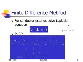
Finite Difference Method • Finite-difference method • Taylor expansion • Finite-difference approximations of derivatives • Applicable to structured grids: spatial location indicated by index • Application to Maxwell’s equations: discretization of the two curl equations or the curl-curl equation Two curl equations Curl-curl equation
Finite-Difference Time-Domain (FDTD) Method • Staggered grids and interleaved time steps for E and H fields • An explicit relaxation solver of Maxwell’s two curl equations • Advantage: efficiency • Disadvantage: stair-case approximation FDTD grids Discretized Maxwell’s equations
Finite-Element Time-Domain (FETD) Method • Both the two curl Maxwell’s equations and the curl-curl equation can be discretized • The curl-curl equation is popular due to reduced number of unknowns • The first step is to discretize the computational domain: mesh generation • Cube • Tetrahedron • Pyramid • Triangular prism
Finite-Element Time-Domain (FETD) Method • Expanding E fields by vector edge-based tangentially continuous basis functions • Enforcement of the curl-curl equation • Strong-form vs. week-form • Weighted residual and Galerkin’s approach • Partition of unity • The final equation to solve
Motivation of the Hybrid Method • FETD vs. FDTD: • Advantages: • Geometry modeling accuracy • Unconditionally stability • Disadvantages • Mesh generation • Computational costs • Hybrid methods: apply more accurate but more expensive methods in limited regions
TD-FE/FD Hybrid Method • Hybrid method: • FETD is mainly used for modeling curved conducting structures • Apply FDTD in inhomogeneous region and boundary truncation • Numerical stability is the most important concern in time-domain hybrid method • Stable hybrid method can be derived by treating the FDTD as a special case of the FETD method
TD-FE/FD Hybrid Method • Let us continue from • Time-domain formulation • Central difference of time derivatives • Newmark-beta method: unconditionally stable when
TD-FE/FD Hybrid Method • Evaluation of elemental matrices • Analytical method • Numerical method • The choice of is also element-wise • FDTD can be derived from FETD
TD-FE/FD Hybrid Method • Cubic mesh and curl-conforming basis functions • The curl of basis functions
TD-FE/FD Hybrid Method • Trapezoidal rule: • First-order accuracy • The lowest-order basis functions are first order functions • The resulting mass matrix is diagonal
TD-FE/FD Hybrid Method • Inversion of the global system matrix • The second-order equation can be reduced to first-order equations by introducing an intermediate variable H • FDTD is indeed a special case of FETD • Cubic mesh • Trapezoidal integration • Choosing • Explicit matrix inversion • Hybridization is natural because choices are local • Pyramidal elements for mesh conformity
TD-FE/FD Hybrid Method • Numerical stability: linear growth of the FETD method • Consider wave propagation in a source-free lossless medium • Spurious solution • The cause of linear growth: • Round-off error • Source injection • Residual error of iterative solvers • Remedies: • Prevention: source conditioning, direct solver etc. • Correction: tree-cotree, loop-cotree etc.
TD-FE/FD Hybrid Method • Spurious reflection on mesh interface due to the different dispersion properties of different meshes • For practical applications, the worst-case reflection is about -40 dB to -35 dB
Automatic Mesh Generation • Three types of meshes are required: tetrahedral, cubic and pyramidal • Transformer: fixed composite element containing tetrahedrons and pyramids • Mesh generation procedure • Generating transformers • Generating tetrahedrons with specified boundary Transformer
Automatic Mesh Generation • Object wrapping: generate transformers and tetrahedral boundaries • Create a Cartesian representation (cells) of the surface • Register surface normal directions at each cell • Cells grow along the normal direction by multiple times • The outmost layer of cells are converted to transformers • Tetrahedral boundaries are generated implicitly Cell representation of surface Surface normal Surface model Tetrahedral boundary
Automatic Mesh Generation Example of multiple open structures
Automatic Mesh Generation • Constrained and conformal mesh generation • Advancing front technique (AFT) • Front: triangular surface boundary • Generate one tetrahedron at a time based on the current front Before tetrahedron generation Search existing points Generate a new point After tetrahedron generation
Automatic Mesh Generation • Practical issues: • What is a valid tetrahedron? • Which front triangle should be selected? • Advantages: • Constrained mesh is guaranteed • Mesh quality is high • Disadvantages: • Relatively slow • Convergence is not guaranteed • Sweep and retry • Adjust parameters
Automatic Mesh Generation Example of single closed object
Automatic Mesh Generation Example of multiple open objects
Mesh Quality Improvement • Mesh quality measure: minimum dihedral angle • Bad mesh quality typically translates to matrix singularity • Dihedral angles are generally required to be between 10o and 170o • Mesh quality improvement: • Topological modification • Edge splitting and removal • Edge and face swapping • Smoothing: smart and optimization-based Laplacian
Mesh Quality Improvement • Edge splitting/removal • Face and edge swapping • Edge swapping is an optimization problem solved by dynamic programming
Mesh Quality Improvement • Laplacian mesh smoothing • Result is not always valid and always improved • Smart Laplacian: position optimization for best dihedral angle
Mesh Quality Improvement • Combined mesh quality optimization: • Smart Laplacian • Edge splitting/removal • Edge and face swapping • Optimization-based Laplacian Before and after smoothing
Mesh Quality Improvement Human head example Dihedral angle distributions CPU time
Mesh Quality Improvement Array example Dihedral angle distributions CPU time
Sparse Cholesky Decomposition • Standard direct solver: LU decomposition • Symmetric positive definite (SPD) matrix and Cholesky decomposition • Matrix fill-in and reordering
Sparse Cholesky Decomposition • Computational complexity of banded matrices is NB2 • Cache efficiency • Reverse Cuthill-McKee and left-looking frontal method
Sparse Cholesky Decomposition Ogive Array BK-16 L45OS BK-12 Examples with single-layer tetrahedral region Oval L225Oval Examples with double-layer tetrahedral region
Computational complexity is O(N1.1) for single-layer tetrahedral meshes and O(N1.7) for double-layer tetrahedral mesh Sparse Cholesky Decomposition Single-layer Double-layer
Scattering Example • Number of Tetrahedrons: 22,383. • CPU time of mesh generation: 60 s. • Min. dihedral: 19.98o • Max. dihedral: 140.17o. • FEM degree of freedom: 41,133. • CPU time of Cholesky: 3.64 s. Surface model. 3D meshes
Scattering Example Mono-static Radar Cross Section at 1.57 GHz
Transmit Antennas in MRI • Goal: to generate homogeneous transverse magnetic fields • Theory of birdcage coil • Sinusoidal current distribution on boundary • Fourier modes of circularly periodic structures • Problems at high fields (7 Tesla or 300 MHz): • Dielectric resonance of human head • Specific absorption rate (SAR)
Transmit Antennas in MRI • Tuned by the MoM method • SAR and field distributions were studied by the hybrid method MoM model Mesh detail Hybrid method model
Transmit Antennas in MRI • Equivalent phantoms are qualitatively good for magnetic field distributions • Inhomogeneous models are required for SAR
Transmit Antennas in MRI • Verification: power absorption at 4.7 Tesla • Experimental setup: • A shielded linear 1-port high-pass birdcage coil at 4.7 Tesla • A 3.5-cm spherical phantom filled with NaCl of different concentrations • Absorbed power to generate a 180o flip angle within 2 ms at the center of the phantom was measured and simulated Result Model
Transmit Antennas in MRI B1 Peak SAR
Receive Antennas in MRI • Single element • Circularly polarized magnetic field • SNR • Antenna array • Combined SNR • Design goal: maximum SNR with maximum coverage
Receive Antennas in MRI Hybrid mesh interface Tetrahedral mesh 32-channel array SNR map Coil and head model
Receive Antennas in MRI Coil model Top Middle Bottom
Conclusions • A TD FE/FD hybrid method was developed • FDTD is a special case of FETD • Relevant choices of FETD method is local • Hybrid mesh generation • Transformers for implicit pyramid generation • Advancing front technique for constrained tetrahedral meshes • Combined approach for mesh quality improvement • Sparse matrix inversion • Profile reduction for banded matrices and cache efficiency • Conformal meshing yields high computational efficiency (O(N1.1) • Future improvement: • Formulations with two curl equations • Adaptive finite-element methods