Download
1 / 25

E N D
1. Free Body Diagrams
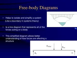
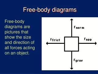
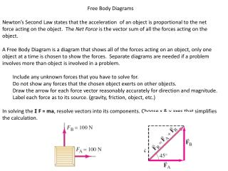
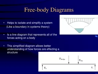
2. Free Body Diagram Every object exists surrounded by other objects, perhaps resting against something, perhaps moving through its surroundings. While an object is in a given environment, it interacts with other objects around it, exerting forces on those objects, and having forces exerted on it.
A free body diagram isolates an object from its environment, or system, and symbolically examines all of the forces acting on the object.
This allows engineers to focus on the forces acting upon the object. From the free body diagram, engineers develop equations which can describe equilibrium, motion, momentum, strength, and many other physical properties.Every object exists surrounded by other objects, perhaps resting against something, perhaps moving through its surroundings. While an object is in a given environment, it interacts with other objects around it, exerting forces on those objects, and having forces exerted on it.
A free body diagram isolates an object from its environment, or system, and symbolically examines all of the forces acting on the object.
This allows engineers to focus on the forces acting upon the object. From the free body diagram, engineers develop equations which can describe equilibrium, motion, momentum, strength, and many other physical properties.
3.
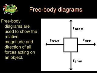
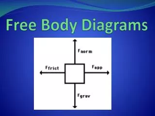
Free Body Diagram Components
4.
Free Body Diagram Components
5. Distance (d) is called the moment arm. It must be measured perpendicular to the line of action of the force. Moment Review
6. Free Body Diagram Procedure
7. Free Body Diagram Procedure 1. Sketch the isolated object. Free body diagrams should be drawn completely isolated from all other objects around it. We �free� the body from its system. Instead of taking time to draw the object in detail, we substitute a simple geometric shape, such as a square or a circle. For these exercises the shape we draw is considered dimensionless.
Free body diagrams should be drawn completely isolated from all other objects around it. We �free� the body from its system. Instead of taking time to draw the object in detail, we substitute a simple geometric shape, such as a square or a circle. For these exercises the shape we draw is considered dimensionless.
8. Free Body Diagram Procedure 2. Sketch the applied and norm forces. Free body diagrams should be drawn completely isolated from all other objects around it. We �free� the body from its system. Instead of taking time to draw the object in detail, we substitute a simple geometric shape, such as a square or a circle. For these exercises the shape we draw is considered dimensionless.
Free body diagrams should be drawn completely isolated from all other objects around it. We �free� the body from its system. Instead of taking time to draw the object in detail, we substitute a simple geometric shape, such as a square or a circle. For these exercises the shape we draw is considered dimensionless.
9. Free Body Diagram Procedure 2. Sketch the applied force and norm forces.
Free body diagrams should be drawn completely isolated from all other objects around it. We �free� the body from its system. Instead of taking time to draw the object in detail, we substitute a simple geometric shape, such as a square or a circle. For these exercises the shape we draw is considered dimensionless.
Free body diagrams should be drawn completely isolated from all other objects around it. We �free� the body from its system. Instead of taking time to draw the object in detail, we substitute a simple geometric shape, such as a square or a circle. For these exercises the shape we draw is considered dimensionless.
10. Free Body Diagram Procedure 3. Label objects and forces. Free body diagrams should be drawn completely isolated from all other objects around it. We �free� the body from its system. Instead of taking time to draw the object in detail, we substitute a simple geometric shape, such as a square or a circle. For these exercises the shape we draw is considered dimensionless.
Free body diagrams should be drawn completely isolated from all other objects around it. We �free� the body from its system. Instead of taking time to draw the object in detail, we substitute a simple geometric shape, such as a square or a circle. For these exercises the shape we draw is considered dimensionless.
11. Free Body Diagram Procedure 4. Label dimensions. Free body diagrams should be drawn completely isolated from all other objects around it. We �free� the body from its system. Instead of taking time to draw the object in detail, we substitute a simple geometric shape, such as a square or a circle. For these exercises the shape we draw is considered dimensionless.
Free body diagrams should be drawn completely isolated from all other objects around it. We �free� the body from its system. Instead of taking time to draw the object in detail, we substitute a simple geometric shape, such as a square or a circle. For these exercises the shape we draw is considered dimensionless.
12. Free Body Diagram Practice
14. Free Body Diagram Practice Free body diagrams are frequently used while solving pulley system problems. It is useful to isolate the parts of a pulley system to discover relationships between the parts. This pulley system consists of an upper fixed pulley, which is supporting block M1, and a lower movable pulley. The movable pulley is supporting block M2. A single rope or cord connects these pulleys. Both pulleys are considered mass-less and frictionless.
A free body diagram of M1 would start with a small shape. Two forces are acting on M1: The weight of M1 and the tension force of the rope.
We can also isolate the pulleys. Looking at the lower movable pulley, we draw the free body. The weight of the block M2 is pulling down on the pulley. Two strands of the rope are pulling up on the pulley, and each of the strands is exerting a tension force.
The tension force in the rope is equal in each free body diagram within the system since there is a single tension force in the entire rope.Free body diagrams are frequently used while solving pulley system problems. It is useful to isolate the parts of a pulley system to discover relationships between the parts. This pulley system consists of an upper fixed pulley, which is supporting block M1, and a lower movable pulley. The movable pulley is supporting block M2. A single rope or cord connects these pulleys. Both pulleys are considered mass-less and frictionless.
A free body diagram of M1 would start with a small shape. Two forces are acting on M1: The weight of M1 and the tension force of the rope.
We can also isolate the pulleys. Looking at the lower movable pulley, we draw the free body. The weight of the block M2 is pulling down on the pulley. Two strands of the rope are pulling up on the pulley, and each of the strands is exerting a tension force.
The tension force in the rope is equal in each free body diagram within the system since there is a single tension force in the entire rope.
15. Different types of support reactions:
Cable, rope, or chain
Pin
Roller
Built-in end � Cantilever Free Body Diagram Reactions
16. Cable, rope, chain � Replace with a tension force only.
Cable Support
17. A sign with weight W is hung by two cables as shown. Draw the FBD of the sign and cables. Cable Support
18. FBD of sign and cables Cable Support
19. Pin � Replaced with TWO reaction forces, one vertical (y) and one horizontal (x). Pin Support
20. Roller � Replaced with ONE reaction force, perpendicular to surface Roller Support
21. Beams and truss bridges are usually supported with one pin support and one roller support. This is called a simply supported object.
Common Support Reactions
22. Built-in-end (cantilever) � Replaced with TWO forces: one horizontal and one vertical, and ONE moment Built-in End Support
23. Contact � Replace with a normal force
Cable, rope, chain � Replace with tension force
Pin � Replace with two reaction forces; one vertical and one horizontal
Roller � Replace with one reaction force perpendicular to surface
Built-in end (cantilever) � Replace with one horizontal force, one vertical force, and one moment Summary Support Reactions
24. Supported with a pin at one end and a roller at the other Truss Bridge FBD
25. FBD of the entire truss bridge Truss Bridge FBD