Download
1 / 79
790 likes | 996 Views
Internetworking. 4.1 Simple Internetworking (IP) 4.2 Routing 4.3 Global Internet 4.4 Multicast. 4.1 Simple Internetworking (IP). 4.1.1 What is an Internework 4.1.2 Service Model 4.1.3 Global Address 4.1.4 Datagram Forwarding in IP 4.1.5 Address Translation (ARP)

E N D
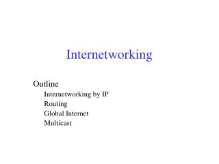
Internetworking 4.1 Simple Internetworking (IP) 4.2 Routing 4.3 Global Internet 4.4 Multicast
4.1 Simple Internetworking (IP) 4.1.1 What is an Internework 4.1.2 Service Model 4.1.3 Global Address 4.1.4 Datagram Forwarding in IP 4.1.5 Address Translation (ARP) 4.1.6 Host Configuration (DHCP) 4.1.7 Error Reporting (ICMP) 4.1.8 Virtual Networks and Tunnels
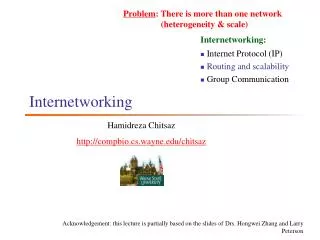
4.1.1 What is an Internework • Concatenation of networks A simple internetwork. Hn =host, Rn = router
An internetwork is a network of networks • in the figure, we see Ethernets, an FDDI ring, and a point-to-point link • each of these is a single-technology network • the nodes that interconnect the networks are called routers (sometimes called gateways) • The following figure shows how H1 and H8 are logically connected by the internet, including the protocol graph running on each node
A simple internetwork of protocol stack Protocol layers used to connect H1 to H8. ETH: the protocol that runs over Ethernet.
4.1.2 Service Model • A good place to start when you build an internetwork is to define its service model • A service model is the host-to-host services you want to provide • Service model for an internetwork • a host-to-host service only if this service can somehow be provided over each of the underlying physical networks
4.1.2 Service Model • IP service model has two parts • addressing scheme • provides a way to identify all hosts in the internetwork • datagram (conectionless) model of data delivery • This service model is sometimes called best effort • although IP makes every effort to deliver datagrams, it makes no guarantees
Datagram • a type of packet sent in a connectionless manner over a network • every datagram carry enough information to let the network forward the packet to its correct destination • no need for any advance setup mechanism to tell the network what to do when the packet arrives
Best-effort delivery (unreliable service) • if something goes wrong and has the following situations • packets are lost • packets are delivered out of order • duplicate copies of a packet are delivered • packets can be delayed for a long time • the network does not make any attempt to recover from the failure
Best-effort, connectionless service is about the simplest service you could ask for from an internetwork • If you provide best-effort service over a network that provides a reliable service, then that’s fine
If, on the other hand, you had a reliable service model over an unreliable network, you would have to put lots of extra functionality into the routers • Keeping the routers as simple as possible was one of the original design goals of IP
Datagram format • a succession of 32-bit words • Packet formats at the internetworking layer and above are almost invariably designed to align on 32-bit boundaries • To simplify the task of processing them in software
Datagram format • a succession of 32-bit words • the top word is transmitted first • the leftmost byte of each word is transmitted first
1st word of the header • Version: the version of IP • the current version of IP is 4 (IPv4) • HLen: the length of the header in 32-bit words • most of the time (when there are no options), the header is 5 words (20 bytes) long
TOS: the 8-bit type of service • allow packets to be treated differently based on application needs • example, the TOS value might determine whether or not a packet should be placed in a special queue that receives low delay
Length: 16 bits of the header • contain the length of the datagram, including the header • the field counts bytes rather than words • the maximum size of an IP datagram is 65,535 bytes • the physical network over which IP is running may not support such long packets • IP supports a fragmentation and reassembly process
2nd word of the header contains information about fragmentation • Offset: 12-bit counts 8-byte chunk, not bytes • the distance (number of chunks) between the start of the original data and the start of the current fragment
3rd word of the header • TTL: one-byte time to live • a specific number of seconds that the packet would be allowed to live • routers along the path would decrement this field until it reached 0 • By default: 64 • Protocol: one-byte demultiplexing key • identifies the higher-level protocol to which this IP packet should be passed • values defined for TCP (6), UDP (17)
Checksum: • calculated by considering the entire IP header as a sequence of 16-bit words • adding them up using ones complement arithmetic, and taking the ones complement of the result
the fourth word of the header: SourceAddr • the fifth word of the header: DestinationAddr • there may be a number of options at the end of the header • the presence or absence of options may be determined by examining the header length (HLen) field
Fragmentation and Reassembly • Each network technology tends to have its own idea of how large a packet can be, example, • Ethernet can accept packets up to 1,500 bytes long • FDDI packets may be 4,500 bytes long • Every network type has a maximum transmission unit (MTU) • the largest IP datagram that it can carry in a frame • this value is smaller than the largest packet size on that network because the IP datagram needs to fit in the payload of the link-layer frame
Fragmentation • typically occurs when necessary (MTU < Datagram) • to enable these fragments to be reassembled at the receiving host, they all carry the same identifier in the Ident field • this identifier is chosen by the sending host and is intended to be unique among all the datagrams that might arrive at the destination from this source over some reasonable time period
since all fragments of the original datagram contain this identifier, the reassembling host will be able to recognize those fragments that go together • should all the fragments not arrive at the receiving host, the host gives up on the reassembly process and discards the fragments that did arrive • IP does not attempt to recover from missing fragments
example • consider what happens when host Hl sends a datagram to host H8 • assuming that the MTU is 1,500 bytes for the two Ethernets, 4,500 bytes for the FDDI network, and 532 bytes for the point-to-point network • a 1,420-byte datagram (20-byte IP header plus 1,400 bytes of data) sent from H1 makes it across the first Ethernet and the FDDI network without fragmentation but must be fragmented into three datagrams at router R2 • these three fragments are then forwarded by router R3 across the second Ethernet to the destination host
1500 532 1500 4500
each fragment is itself a self-contained IP datagram that is transmitted over a sequence of physical networks, independent of the other fragments • each IP datagram is reencapsulated for each physical network over which it travels
(a) (b) Header fields used in IP fragmentation: (a) unfragmented packet; (b) fragmented packets.
The unfragmented packet has 1,400 bytes of data and a 20-byte IP header • when the packet arrives at router R2, which has an MTU of 532 bytes, it has to be fragmented • a 532-byte MTU leaves 512 bytes for data after the 20-byte IP header, so the first fragment contains 512 bytes of data • the router sets the M bit as 1 in the Flags field, meaning that there are more fragments to follow • it sets the Offset to 0, since this fragment contains the first part of the original datagram
the data carried in the second fragment starts with the 513th byte of the original data, so the field in this header is set to 64 (= 512/8) • the third fragment contains the last 376 bytes of data, and the offset is now 2 × 512 / 8 = 128 (since this is the last fragment, the M bit is not set)
4.1.3 Global Addresses • One of the things that IP service model provides is an addressing scheme • If you want to be able to send data to any host on any network, there needs to be a way of identifying all the hosts • Thus, we need a global addressing scheme– one in which no two hosts have the same address
4.1.3 Global Addresses • Ethernet addresses are globally unique • that alone does not suffice for an addressing scheme in a large internetwork • Ethernet addresses are also flat • they have no structure and provide very few clues to routing protocols
IP addresses are hierarchical • made up of two parts that correspond to some sort of hierarchy in the internetwork • network part • identifies the network to which the host is attached • all hosts attached to the same network have the same network part • host part • identifies each host uniquely on that particular network
example 1 • the addresses of the hosts on network 1 would all have the same network part and different host parts • example 2 • the routers are attached to two networks • they need to have an address on each network, one for each interface, e.g., router Rl • has an IP address on the interface to network 2 that has the same network part as the hosts on network 2 • has an IP address on the interface to network 3 that has the same network part as the hosts on network 3 • it is more precise to think of IP addresses as belonging to interfaces than to hosts
IP addresses are divided into three different classes • each of the following figure defines different-sized network and host parts • there are also class D addresses specify a multicast group, and class E addresses that are currently unused • in all cases, the address is 32 bits long
7 24 A: 0 Network Host 14 16 B: 1 0 Network Host 21 8 C: 1 1 0 Network Host IP addresses: (a) class A; (b) class B; (c) class C
the class of an IP address is identified in the most significant few bits • if the first bit is 0, it is a class A address • if the first bit is 1 and the second is 0, it is a class B • if the first two bits are 1 and the third is 0, it is a class C address • of the approximately 4 billion (= 232)possible IP addresses • one-half are class A • one-quarter are class B • one-eighth are class C
Class A addresses • 7 bits for the network part and 24 bits for the host part • 126 (= 27-2) class A networks (0 and 127 are reserved) • each network can accommodate up to 224-2 (about 16 million) hosts (again, two are reserved values) • Class B addresses • 14 bits for the network part and 16 bits for the host part • 65,534 (= 216-2) hosts
Class C addresses • 21 bits for the network part and 8 bits for the host part • 2,097,152 (= 22l) class C networks • 254 hosts (host identifier 255 is reserved for broadcast, and 0 is not a valid host number)
IP addresses are written as four decimal integers separated by dots • each integer represents the decimal value contained in 1 byte (= 0~255) of the address, starting at the most significant • Example, 171.69.210.245 • Internet domain names (DNS) • also hierarchical • domain names tend to be ASCII strings separated by dots, e.g., cs.princeton.edu
4.1.4 Datagram Forwarding in IP • Forwarding • the process of taking packet from an input and sending it out on the appropriate output • Routing • the process of building up the tables that allow the correct output for a packet to be determined • The discussion here focus on forwarding
Strategy • every IP datagram contains destination’s address • if connected to destination network • then forward to host • if not directly connected • then forward to some router • forwarding table maps network number (NetworkNum) into next hop (NextHop) • each host has a default router • each router maintains a forwarding table
Datagram forwarding algorithm • if (NetworkNum of destination = NetworkNum of one of my interfaces) then deliver packet to destination over that interface else if (NetworkNum of destination is in my forwarding table) then deliver packet to NextHop route else deliver packet to default router
For a host with only one interface and only a default router in its forwarding table (simplified algorithm) • if (NetworkNum of destination = my NetworkNum) then deliver packet to destination directly else deliver packet to default router
Example1 • suppose H1 wants to send a datagram to H2 • since they are on the same physical network, H1 and H2 have the same network number in their IP address • H1 deduces that it can deliver the datagram directly to H2 over the Ethernet • the one that needs to be resolved is how Hl finds out the correct Ethernet address for H2
Example2 • suppose H1 wants to send a datagram to H8 • since they are on different physical networks • H1 deduces that it needs to send the datagram to a router • Hl sends the datagram over the Ethernet to R1 • R1 knows that it cannot deliver a datagram directly to H8 because neither of Rl’s interfaces is on the same network as H8
suppose R1’s default router is R2; R1 then sends the datagram to R2 over the token ring network • assume R2 has the forwarding table shown as follows, it looks up H8’s network number (network 1) and forwards the datagram to R3
R3 forwards the datagram directly to H8 • it is possible to include the information about directly connected networks in the forwarding table • example, we could label the network interfaces of router R2 as interface 0 for the point-to-point link (network 4) and interface l for the token ring (network 3) 0 1