Download
1 / 36
480 likes | 1.08k Views
Grid synchronization for power converters. Marco Liserre liserre@poliba.it. Outline. Grid requirements for DG inverters PLL Basics, PLL in power systems Design of PLL PLL for single-phase systems Methods to create the orthogonal component Methods using adaptive filters

E N D
Grid synchronization for power converters Marco Liserre liserre@poliba.it
Outline • Grid requirements for DG inverters • PLL Basics, PLL in power systems • Design of PLL • PLL for single-phase systems • Methods to create the orthogonal component • Methods using adaptive filters • PLL for three-phase systems • Conclusions • Reference papers
Grid Distrurbances Grid disturbances are not at all a new issue, and the utilities are aware of them. However, they have to take a new look because of the rapidly changing customers’ needs and the nature of loads (CIGRE WG14-31, 1999) Thomsen,1999; CIGRE WG14-31, 1999
The following conditions should be met, with voltages in RMS and measured at the point of utility connection. Grid requirements for DG inverters • When the utility frequency is outside the range of +/- 1 Hz the inverter should cease to energize the utility line within 0.2 seconds. • The PV system shall have an average lagging power factor greater than 0,9 when the output is greater than 50% rated. • Thus the grid voltage and frequency should be estimated and monitored fast and accurate enough in order to cope with the standard
A good synchronization of the current with the grid voltage is necessary as: • the standards require a high power factor (> 0.9) • a ”clean” reference for the current is necesarry in order to cope with the harmonic requirements of grid standards and codes • grid connection transients needs to be minimized in order not to trip the inverter • Distributed Generation systems of higher power have also requirements in terms of voltage support or reactive power injection capability and of frequency support or active power droop • Micro-grid distributed generation systems have wider range of voltage and frequency and the estimated grid voltage parameters are often involved in control loops Grid synchronization requirements
There are two basical synchronization methods: • Filtered Zero Cross Detection (ZCD) • PLL Single-phase systems: • The classical solution for single-phase systems was Filtered ZCD as for the PLL two orthogonal voltages are required. • The trend now is to use the PLL technique also by creating ”virtual” orthogonal components using different techniques! Three-phase systems: • Three-phase PLL should deal with unbalnace hence with negative sequence • Moreover in three-phase systems dynamics would be better if synchronizing to all three phase voltages, i.e. based on space vectors rather then on a scalar voltage Grid synchronization options and challenges
Dual point interpolation circuit Zero Cross Detection (ZCD) circuits Resistive feedback hysteresis circuit Dynamic hysteresis comparator circuit Source: R.W. Wall, “Simple methods for detecting zero crossing,” IEEE IECON’03, pp. 2477-2481
Filtered Zero Cross Detection (ZCD) based monitoring and synchronization • Filtering introduces delay. There are digital predictive FIR filters without delay bu with high complexity (very high order!) • The RMS voltage and frequency are calculated once in a period à poor detection of changes (sags, dips, etc.)
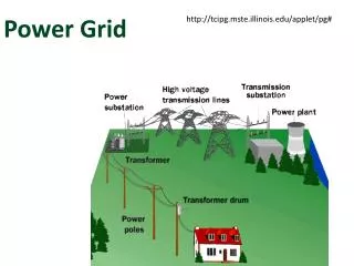
PLL basis Basic idea of synchronization based on a phase-locked loop: • Phase-locked technology is broadly used in military, aerospace, consumer electronics systems where some kind of feedback is used to synchronize some local periodic event with some recognizable external event • Many biological processes are synchronized to environmental events. Actually, most of us schedule our daily activities phase-locking timing information supplied by a clock. • A grid connected power converter should phase-lock its internal oscillator to the grid voltage (or current), i.e., an amplitude and phase coherent internal signal should be generated. Phase-locked synchronization(continuous, predictive,…) Event based synchronization(simple, discontinuous, …)
PLL basis Basic blocks: • Phase Detector (PD). This block generates an output signal proportional to the phase difference between its two input signals. Depending on the type of PD, high frequency ac components appear together the dc phase difference signal. • Loop Filter (LF). This block exhibits low pass characteristic and filters out the high frequency ac components from the PD output. Typically this is a 1-st order LPF or PI controller. • Voltage Controlled Oscillator (VCO). This block generates at its output an ac signal whose frequency varies respect a central frequency as a function of the input voltage.
PLL in power systems In 1968 Ainsworth proposed to use a voltage controlled oscillator (VCO) inside the control loop of a High Voltage Direct Current (HVDC) transmission system to deal with the novel, at that time, harmonic instability problem. Subsequently, analog phase locked loops (PLL) were proposed to be used as measurement blocks, which provide frequency adaptation in motor drives.
Phase Locked Loop tuning Reference: VCO output: VCO angle: PD/Mixer output: if , then , Small signal analysis: if , then , The average value is
Phase Locked Loop tuning assuming then with that can be written as The PLL can be tuned as function of the damping and of the settling time
Key parameters of the PLL • The hold range DwH is the frequency range at which a PLL is able to maintain lock statically. For the PI, LF(0)=∞ and the hold range is only limited by the frequency range of the VCO • The pull-in range DwP is the frequency range at which a PLL will always became locked, but the process can become rather slow. For the PI loop filter this range trends to infinite. Pull-in time: • The lock range DwL is the frequency range within which a PLL locks within one-single beat note between the reference frequency and the output frequency. Lock-in time:
Phase Locked Loop: the need of the orthogonal component To eliminate the 2° harmonic oscillation from and obtain it should be considered that
Park transformation in the PD Park transformation: Assuming win=wout :
Park transformation in the PD PI on vd PI on vq From here on, it will be considered: and PI on vq,, i.e., Therefore:
Methods to create the orthogonal component • Transport Delay T/4 • The transport delay block is easily implemented through the use of a first-in-first-out (FIFO) buffer, with size set to one fourth the number of samples contained in one cycle of the fundamental frequency. • This method works fine for fixed grid frequency. If the grid frequency is changing with for ex +/-1 Hz, then the PLL will produce an error • If input voltage consists of several frequency components, orthogonal signals generation will produce errors because each of the components should be delayed one fourth of its fundamental period.
Methods to create the orthogonal component • Inverse Park Transformation • A single phase voltage (va) and an internally generated signal (vb’) are used as inputs to a Park transformation block (αβ-dq). The d axis output of the Park transformation is used in a control loop to obtain phase and frequency information of the input signal. • vb’ is obtained through the use of an inverse Park transformation, where the inputs are the d and q-axis outputs of the Park transformation (dq-αβ). fed through first-order low pass filters. • Although the algorithm of the PLL based on the inverse Park transformation is easily implemented, requiring only an inverse Park and two first-order low-pass filters
Methods to create the orthogonal component • Second Order Generalized Integrator
Methods using adaptive filters • Adaptive Notch Filter (ANF) • vout=0 when: • voutcan not be directly used as PD in the PLL • vout=0 when: • voutcan be used as PD in the PLL
Methods using adaptive filters • ANF-based PLL • Very sensible to frequency variation • ANF+PLL EPLL • Combination of an ANF with a conventional PLL gives rise to the Enhanced PLL (EPLL) • More robust • Faster dynamic response
Methods using adaptive filters • Enhanced PLL (EPLL) • Original structure of the EPLL
Methods using adaptive filters • SOGI-PLL Adaptive band-pass filter: Damping factor is a function of the detected frequency value Second order generalized integrator follower: If w’ can change, SOGI follower can be seen as an adaptive band-pass filter with damping factor set by k and unitary gain • As in the EPLL, a standard PLL can be used to detect grid frequency and angle • ju is 90º-leading v’ when the PLL is synchronized in steady state • ju=-qu and qu qv’ • It seems intuitive to use -qu (instead ju) as the feedback signal for the PD of the PLL
Methods using adaptive filters • SOGI-based Frequency Locked Loop (SOGI-FLL) • Does not need any trigonometric function since neither synchronous reference frame nor voltage controlled oscillator are used in its algorithm. • Is frequency-adaptive by using a FLL and not a PLL. • Is highly robust in front of transient events since grid frequency is more stable than voltage phase-angle. • Attenuates high-order harmonics of the grid voltage. • Entails light computational burden, using only five integrators for detection of both sequence components.
Three-phase grid synchronization Distorted and unbalanced voltage vector Neither constant amplitude nor rotation speed
Characterization of voltage dips • Phase-voltages from characteristic parameters • Sequence components from characteristic parameters
Three-phase grid synchronization Three-phase Synchronous Reference Frame PLL Balanced voltage Unbalanced voltage
Three-phase grid synchronization Three-phase Synchronous Reference Frame PLL Near of synchronization: The SRF is not able to track instantaneous evolution of the voltage vector when the PLL bandwidth is low
Three-phase grid synchronization Three-phase Synchronous Reference Frame PLL Setting a low PLL bandwidth and using a low-pass filter it is possible to obtain a reasonable approximation of the positive sequence voltage but the dynamic is too slow. Advanced filtering strategies can be used to cancel out the double frequency oscillation keeping high locking dynamics, e.g., a repetitive controller based on a DFT algorithm. Additional improvements are added to these filters to make them frequency adaptive.
Three-phase grid synchronization Decoupled Doubled SRF-PLL. Decoupling Near of synchronization: This terms act as interferences on the SRF dqn rotating at nw frequency and viceversa Generic decoupling cell:
Three-phase grid synchronization Decoupled Doubled SRF-PLL PLL input normalization y .
Conclusions • PLL is a very useful method that enable the grid inverters to: • Create a "clean" current reference synchronized with the grid • Comply with the grid monitoring standards • The PLL generate is able to track the frequency and phase of the input signal in a designed settling time • By setting a higher settling time a "filtering" effect can be achieved in order to obtain a "clean" reference even with a polluted grid. • Some PLLs need two signals in quadrature at the input. • For single-phase systems as there is only one signal available, the orthogonal signal needs to be created artificially. • Transport Delay, Inverse Park Transformation, or Second Order Generalized Integrators are some the methods used for quadrature signal generation. • Adaptive notch filters canceling fundamental utility frequency are used as phase detectors in PLLs • FLL based on a SOGI is a very effective method for single phase synchronization
J. D. Ainsworth, “The phase-locked oscillator-a new control system for controlled static convertors,” IEEE Transactions on Power Apparatus and Systems, vol. 87, no. 3, pp. 859-865, Mar. 1968. • G. C. Hsieh, J. C. Hung, Phase-locked loop techniques – A survey, IEEE Trans. On Ind. Electronics, vol.43, pp.609-615, Dec.1996. • F. M. Gardner, Phase Lock Techniques. New York: Wiley, 1979. • L. D. Zhang, M. H. J. Bollen Characteristic of voltage dips (sags) in power systems, IEEE Trans. Power Delivery, vol.15, pp.827-832, April 2000. • F. Blaabjerg, R. Teodorescu, M. Liserre, and A. V. Timbus, “Overview of Control and Grid Synchronization for Distributed Power Generation Systems”, IEEE Trans. on Ind. Electronics, Vol. 53, Oct. 2006 Page(s):1398 – 1409 • M. K. Ghartemani, M.R. Iravani, “A method for synchronization of power electronic converters in polluted and variable-frequency environments,” IEEE Trans. Power Systems, vol. 19, pp. 1263-1270, Aug. 2004. • M.K. Ghartemani, M.R. Iravani, “A Method for Synchronization of Power Electronic Converters in Polluted and Variable-Frequency Environments,” IEEE Trans. Power Systems, vol. 19, Aug. 2004, pp. 1263-1270. • H.-S. Song and K. Nam, “Dual current control scheme for PWM converter under unbalanced input voltage conditions,” IEEE Trans. On Industrial Electronics, vol. 46, no. 5, pp. 953–959, 1999. References
P. Rodríguez, A. Luna, I. Candela, R. Teodorescu, and F. Blaabjerg, “Grid Synchronization of Power Converters using Multiple Second Order Generalized Integrators,” IECON’08, Nov. 2008. • P. Rodríguez, J. Pou, J. Bergas, J.I. Candela, R. Burgos and D. Boroyevich, “Decoupled Double Synchronous Reference Frame PLL for Power Converters Control,” IEEE Trans. on Power Electronics, March 2007. • P. Rodriguez, R. Teodorescu, R.; I. Candela, I.; A.V. Timbus, M. Liserre, F. Blaabjerg, “New Positive-sequence Voltage Detector for Grid Synchronization of Power Converters under Faulty Grid Conditions,” PESC '06, June 2006. • M Ciubotaru, Teodorescu, R., Blaabjerg, F., “A New Single-Phase PLL Structure Based on Second Order Generalized Integrator”, PESC’06, June 2006. • P. Rodríguez, A. Luna, M. Ciobotaru, R. Teodorescu, and F. Blaabjerg, “Advanced Grid Synchronization System for Power Converters under Unbalanced and Distorted Operating Conditions,” IECON’06, Nov. 2006. • S.-K. Chung, “Phase-Locked Loop for grid-connected three-phase power conversion systems,” IEE Proceedings on Electronic Power Applications, vol. 147, no. 3, pp. 213–219, 2000. • Francisco Daniel Freijedo Fernández, “Contributions to Grid-Synchronization Techniques for Power Electronic Converters”, PhD Thesis, Vigo University, Spain, 2009 References
Part of the material is or was included in the present and/or past editions of the “Industrial/Ph.D. Course in Power Electronics for Renewable Energy Systems – in theory and practice” Speakers: R. Teodorescu, P. Rodriguez, M. Liserre, J. M. Guerrero, Place: Aalborg University, Denmark The course is held twice (May and November) every year Acknowledgment