Download
1 / 47
470 likes | 589 Views
Processor Structure & Operations of an Accumulator Machine. Andres Ochoa CSCI 6303 Principles of Information Technology. Outline. CPU Control Unit ALU Registers Bus Fetch-Execute Cycle Pipelining Accumulator. CPU. CPU Control Unit ALU Requires memory within CPU itself Registers

E N D
Processor Structure&Operations of an Accumulator Machine Andres Ochoa CSCI 6303 Principles of Information Technology
Outline • CPU • Control Unit • ALU • Registers • Bus • Fetch-Execute Cycle • Pipelining • Accumulator
CPU • CPU • Control Unit • ALU • Requires memory within CPU itself • Registers • Data transfer within CPU, and external devices • Buses
Control Unit • Coordinates all activities within the CPU • Controls CPU Operations • ALU Operations • Movement of Data within CPU • Exchange of Data and Control Signals across external interfaces (ex. Main Memory) • Functional requirements • Operations, Addressing, Registers, I/O, Memory Interface, Interrupt Processing
Arithmetic / Logic Unit (ALU) • Calculator within the CPU • Data Processing • Performs… • Arithmetic operations • Addition, Subtraction, Multiplication, Division • Example: AX = 0000 1010, BX = 0000 0101 • ADD destination, source • ADD ax, bx • AX = 0000 1111 • Logic operations • AND, OR, NOT, XOR • Example: AX = 0101 0101, BX = 0000 0001 • AND destination, source • AND ax, bx • AX = 0000 0001
Register • Register • CPU memory • Divided into different registers for general and specific use
Registers • High-Speed Memory within the CPU • General-Purpose • Address, Operand, • Data • Hold Data • Address • Pointers, Index registers • Status • Flags (Ex. zero, carry, overflow…)
Four Essential Registers • Control Registers • Program Counter • Address (location) of next instruction • Instruction Register • Actual instruction being executed • Memory Address Register (MAR) • Address of location in memory • Memory Buffer Register (MBR) • Contains word of data to be written to memory • Holds word of data read from memory
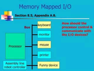
Bus • Connections within CPU, and between the CPU and external devices • Composed of multiple wires or traces • Three main buses external to CPU • Control Bus • Address Bus • Data Bus
Bus Functions • Control Bus • Carries the control unit’s signal to external devices (read, write, start, stop, etc) • Address Bus • Carries the address of location in memory • MAR – memory address register • Data Bus • Carries data from memory to CPU, or from CPU to memory • MBR – memory buffer register
The Data Bus transfers a word from the CPU to memory, and from memory to the CPU. In order for a word to go in and out of a CPU, it has to be loaded into the MBR. A word is brought in from the Data Bus into the MBR, which can be transferred to other registers in the CPU. Also, a word needs to be loaded into the MBR before it goes out of the CPU and through the Data Bus. Bus Operations (Data Bus)
The Address Bus allows the CPU to locate a word in memory. The address is loaded into the MAR and is sent through the Address Bus. The address sent through the bus will point at a specific location in memory. Bus Operations (Address Bus)
The Control Bus allows the CPU to tell memory or any other external components what to do. For example, if a word needs to be read from memory or written to memory, the Control Unit will send a signal through the Control Bus which tells the memory whether it is a read or write command. Bus Operations (Control Bus)
Example (Fetch Instruction) • The Program Counter contains the address of the next instruction. • The address is loaded into the Memory Address Buffer (MAR).
Example (Fetch Instruction) • The MAR sends the address through the Address Bus to locate the next instruction in memory.
Example (Fetch Instruction) • The Control Unit sends a command through the Control Bus to memory. • The command tells the memory that the CPU will read a word from memory.
Example (Fetch Instruction) • The word is read from memory and sent through the Data Bus into the Memory Buffer Register (MBR). • This word of data is the next instruction.
Example (Fetch Instruction) • The instruction is then transferred from the MBR to the Instruction Register (IR).
Bus Problems • Bus Bottleneck • Only one word of data can be passed through the bus at a time • All devices need to communicate • If multiple buses were used, the number of wires needed would be too many • Too complex and unmanageable • Single interconnecting bus is used • All components communicate using the same bus
Fetch-Execute Cycle • Fetch Instruction • Decode Instruction • Calculate Operands • Fetch Operands • Execute Instruction • Write Data
Fetch-Execute Cycle • Fetch Instruction • Address from Program Counter is loaded into the MAR • Processor reads instruction from memory • Instruction is fetched and stored into the MBR • Instruction moved from MBR to IR • Decode Instruction • Instruction is decoded to determine opcode and operand specifiers • Determine what action is required
Fetch-Execute Cycle • Calculate Operands • Calculates address (location) of each operand, whether it’s from main memory or already in a register. • Fetch Operands • Memory • Needs to be fetched from memory. • Slower to retrieve • Registers • Operands in registers don’t have to be fetched • Already in the CPU registers and faster to access
Fetch-Execute Cycle • Execute Instruction • Perform specified operation and store in destination operand location • ALU – performs arithmetic operations • Write Data • Result is written to memory • Program Counter is incremented to locate the next instruction
Fetch-Execute Cycle Start
Pipelining • Concept • Assembly Line • Since instructions are processed in different stages, pipelining is used • Increase speed of CPU significantly • Instruction process can be broken up into multiple stages • Six stages are mentioned • Fetch Instruction, Decode Instruction, Calculate Operands, Fetch Operands, Execute Instruction, Write Data
Fetch-Execute Cycle (without Pipelining) • Assumptions for this example: • All stages last the same amount of time • One instruction at a time
Fetch-Execute Cycle (without Pipelining) • Stage 1: Fetch Instruction • Stage 2: Decode Instruction • Stage 3: Calculate Operands • Stage 4: Fetch Operands • Stage 5: Execute Instruction • Stage 6: Write Data
Fetch-Execute Cycle (without Pipelining) • Stage 1: Fetch Instruction • Stage 2: Decode Instruction • Stage 3: Calculate Operands • Stage 4: Fetch Operands • Stage 5: Execute Instruction • Stage 6: Write Data
Fetch-Execute Cycle (without Pipelining) • Stage 1: Fetch Instruction • Stage 2: Decode Instruction • Stage 3: Calculate Operands • Stage 4: Fetch Operands • Stage 5: Execute Instruction • Stage 6: Write Data
Fetch-Execute Cycle (without Pipelining) • Stage 1: Fetch Instruction • Stage 2: Decode Instruction • Stage 3: Calculate Operands • Stage 4: Fetch Operands • Stage 5: Execute Instruction • Stage 6: Write Data
Fetch-Execute Cycle (without Pipelining) • Stage 1: Fetch Instruction • Stage 2: Decode Instruction • Stage 3: Calculate Operands • Stage 4: Fetch Operands • Stage 5: Execute Instruction • Stage 6: Write Data
Fetch-Execute Cycle (without Pipelining) • Time is wasted going through the entire cycle on a single instruction
Pipeline Concept • Assumptions for this example: • All stages last the same amount of time • All instructions are the same
Pipeline Concept • Stage 1: Fetch Instruction • Stage 2: Decode Instruction • Stage 3: Calculate Operands • Stage 4: Fetch Operands • Stage 5: Execute Instruction • Stage 6: Write Data
Pipeline Concept • Stage 1: Fetch Instruction • Stage 2: Decode Instruction • Stage 3: Calculate Operands • Stage 4: Fetch Operands • Stage 5: Execute Instruction • Stage 6: Write Data
Pipeline Concept • Stage 1: Fetch Instruction • Stage 2: Decode Instruction • Stage 3: Calculate Operands • Stage 4: Fetch Operands • Stage 5: Execute Instruction • Stage 6: Write Data
Pipeline Concept • Stage 1: Fetch Instruction • Stage 2: Decode Instruction • Stage 3: Calculate Operands • Stage 4: Fetch Operands • Stage 5: Execute Instruction • Stage 6: Write Data
Pipeline Concept • Stage 1: Fetch Instruction • Stage 2: Decode Instruction • Stage 3: Calculate Operands • Stage 4: Fetch Operands • Stage 5: Execute Instruction • Stage 6: Write Data
Pipeline Concept • Faster CPU speed • Time is used efficiently • In real CPU, not all stages are the same • Instructions can be simple or complex • Certain stages can be faster or slower than others
Pipelining • The concept of pipelining is to split each process of the Fetch-Execute cycle into independent stages handling different instructions. • As the previous example shows, each stage is handling the process of a different instruction. • This means that instructions are completed one after another, instead of going through the entire cycle for one single instruction. • However, some stages might be faster than others. • Stages involving the fetching of instructions or operands and storing into memory will take more time, so one stage might be waiting on another stage in front of it to finish.
Accumulator Machine • Almost all early computers were accumulator machines. • An Accumulator Machine is a CPU that stores most of the results from the ALU calculations into an Accumulator Register. • Examples of Accumulator Machines • PIC microcontroller • Modern CPUs are typically 2-operand or 3-operand machines • The operands also specify the source and destination • AX • General-Purpose Register • Arithmetic, logic, data transfer • Not considered accumulator machines
Accumulator • Accumulator • Type of Register • Stores the result of ALU • Without the accumulator, the result would be stored in memory and read again for other operations. • Accumulator allows the ALU result to be stored in a register so it can be quickly accessed again.
Accumulator • Accumulator Register • Implicit operand for arithmetic instructions • Example: ADD memaddress • Value added with accumulator value • Implicit destination of the operand • Example: ADD memaddress • Result is stored in accumulator • Note: In modern processors, not all arithmetic instructions automatically use the accumulator register.
Instructions using Accumulators in Modern Processors • Multiplication • AX multiplied by source operand, and then stored into AX. • Example: • AX = 0000 0101 • BX = 0000 0011 • MUL BX • Answer AX = 0000 1111 • Division • AX divided by source operand, and then stored into AX • Example: • AX = 0000 1111 • BX = 0000 0011 • DIV BX • Answer AX = 0000 0101
Works Cited • Accumulator (computing). 24 Sept. 2008 <http://en.wikipedia.org/wiki/accumulator_(computing)>. • Englander, Irv. The Architecture of Computer Hardware and System Software : An Information Technology Approach. New York: Wiley, 2003. 132-86. • Stallings, William. Computer Organization and Architecture : Designing for Performance. Upper Saddle River: Prentice Hall, 2005. 416-59. • Williams, Robert. Computer Systems Architecture : A Networking Approach. New York, NY: Addison-Wesley Longman, Limited, 2000. 47-112.
Processor Structure&Operations of an Accumulator Machine End of Presentation