Download
1 / 114
1.16k likes | 1.67k Views
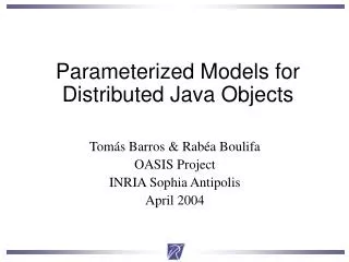
Reduced Order Modeling of Parameterized and Distributed Systems. Luca Daniel, M.I.T. Parameterized Model Order Reduction. Problem Classification Reducing Linear Systems Moment Matching with Linear parameters Moment Matching with NON-linear parameters Quasi Convex Optimization approach

E N D
Reduced Order Modeling of Parameterized and Distributed Systems Luca Daniel, M.I.T.
Parameterized Model Order Reduction • Problem Classification • Reducing Linear Systems • Moment Matching with Linear parameters • Moment Matching with NON-linear parameters • Quasi Convex Optimization approach • Reducing NON-linear systems • Moment Matching with NON-linear parameters
4 10 3 10 |Z(f)| 2 10 1 10 • Field solvers can produce instance impedance vs. frequency curves. 0 10 6 7 8 9 10 10 10 10 10 10 frequency Motivation. Example: Analysis of RF micro-inductor • How are the substrate eddy currents affecting the quality factor of the inductor? • How are the displacement currents affecting the resonance of the inductor? • Need to capture all 2nd order effects
Motivation Example: MOR of RF micro-inductor I ADC LNA ADC Q LO • “Model Order Reduction” can help verify how the inductor performance (Q, resonance position, etc) affect the transceiver performance (distortion, interference rejection etc.) • Modeling Requirements: • as accurate as a field solver • automatic and robust • model compatible with circuit simulators
Motivation Example: Parameterized MOR of RF micro-inductor I ADC LNA ADC Q LO d • “Model Order Reduction” can help verify how the resonator or inductor performance (noise, quality factor, etc)affect the transceiver performance (distortion, interference rejection) W • “Parameterized Model Order Reduction” can help verify how the transceiver performance changeswhen I change wire widths and wire separation
MotivationExample. Analysis of Integrated Power Electronics How is the magnetic fringing field from the core effecting eddy current losses? Analysis tools can produce for instance resistance vs. frequency curves. Rac Spattered laminated NiFe core, electroplated windings [Daniel96] frequency [Hz]
Micro-inductor in a DC/DC power converter Vin(t) Vout(t) • “Model Order Reduction” can help verifying how the 2nd order effects of the power inductor (e.g. power loss vs. freq. curve)influences the power converter functionality (dynamics, overall power efficiency) • “Parameterized Model Order Reduction” can help verify how the functionality and the efficiency of the overall power converter changeswhen I change wire widths and wire separations?
1M equations 10 equations From Field Solvers to Parameterized Model Order Reduction (PMOR). Field Solvers discretize geometry and produce large systems d W PMOR • PMOR produces a dynamical model: • automatically • match port impedance • small (10-15 ODEs)
matrix size linearity # parameters Parameterized model order reduction.Problem classification
Parameterized Model Order ReductionProblem Classification matrix size Non-Linear Systems Linear Time Invariant non-linearly parameterized linearly parameterized linearity # parameters
ADC LO LNA Parameterized Model Order Reduction.Applications interconnect MEMS RF inductors matrix size Packages Linear Time Invariant Non-Linear Systems linearly parameterized non-linearly parameterized linearity # parameters
ADC LO LNA Parameterized Model Order Reduction.Previous work interconnect MEMS RF inductors matrix size Packages Linear Time Invariant Non-Linear Systems linearly parameterized non-linearly parameterized Moment Matching: Pullela97, Weile99, Gunupudi00, Prud’homme02, Daniel02, Li05 linearity • statistical data mining • Liu DAC99 • Heydari ICCAD01 • CMU Rutenbar02 # parameters
Parameterized Model Order Reduction • Problem Classification • Reducing Linear Systems • Moment Matching with Linear parameters • Moment Matching with NON-linear parameters • Quasi Convex Optimization approach • Reducing NON-linear systems • Moment Matching with NON-linear parameters
Motivation for geometrically parameterized modeling of interconnect • In interconnect design often would like: • reliable functionality: • minimize capacitive cross-talk, • minimize inductive cross-talk, • minimize electromagnetic interference • high speed: • minimize resistance • minimize capacitance • low cost: • minimize area • Need to explore tradeoff space and find optimal design!
The traditional design methodology • The traditional design flow: • REPEAT • design all interconnect wires • extract accurately parasitics all at once • UNTIL noise and timing are within specs • such procedure is not ideal for optimization! • each iteration is very time consuming
Alternative design methodologies • Pre-characterize standard interconnect structures (e.g. busses): • using parasitic extraction and table lookup • or building parameterized and accurate low order models • However... if the model construction is fast enough can also: • build the interconnect structure model "on the fly" during layout • accounting for any topology in surrounding topologies already committed to layout • then use optimizer to choose the best parameter for optimal tradeoff design.
accounting for surrounding topology Example: an interconnect bus • We construct a multi-parameter model of the bus parameterized in wire width W and separation d W d …………..
Conductance matrix Parasitic extraction produces large state space models • E.g. subdividing wires in short sections and using for instance Nodal Analysis ………….. Large linear dynamical system
construct a reduced order system with similar frequency response Our goal • Given a large parameterized linear system:
Construct a linear system model with: • smaller complexity • same fidelity • small reduction cost 20 x 20 BackgroundNon-parameterized Model order reduction • Given a large linear system model: 500,000 x 500,000
BackgroundModel order reduction (cont.) Taylor series expansion: • change basis and use only the first few vectors of the Taylor series expansion: equivalent to match first derivatives around expansion point U
qxn nxn nxq nxq qxq Reducing matrices’ size: Congruence Transformation [PRIMA TCAD98]
Parameterized Model Order Reduction. Example: interconnect bus • Discretizing wires and using Nodal Analysis …………..
More in general...[D. TCAD04] [D. PhD04] • It is a p-variables Taylor series expansion Uq Once again change basis: • use first few vectors of the Taylor expansion, • matching first few derivatives with respect to each parameter
Parameterized moment matching (cont.) Congruence transformations on each of the matrices qxn qxq nxn nxq
W0=1um d0 =1um W0=1um d0=1um W=0.25um W=0.2um W=4um W=8um W=0.25um W=0.2um W=4um W=8um d=0.25um d=2um Example: model step responses for different W and d. ………….. N=16 wires h=1.2um L=1mm W d
W0=1um d0 =1um W=0.25um W=0.2um W=4um W=8um W=0.25um W=0.2um W=4um W=8um W0=1um d0 =1um d=2um d=0.25um Example: model crosstalk responsesfor different W and d. ………….. N=16 wires h=1.2um L=1mm W d
Parameterized Model Order Reduction • Problem Classification • Reducing Linear Systems • Moment Matching with Linear parameters • Moment Matching with NON-linear parameters • Quasi Convex Optimization approach • Reducing NON-linear systems • Moment Matching with NON-linear parameters
ADC LO LNA Example: RF inductorReduction of Non-linearly parameterized linear systems interconnect MEMS RF inductors matrix size Linear Time Invariant Non-Linear Systems linearly parameterized non-linearly parameterized Moment Matching Pullela97, Weile99, Prud’homme 02 linearity • statistical data mining • Liu DAC99 • Heydari ICCAD01 • CMU Rutenbar02 # parameters
Example: RF inductor • Design parameters: • wire dimensions and separations, • number of turns • type of substrate and distance from wires • Performance parameters: • inductance • quality factor Q • resonance frequency • power • area • Effects captured: • displacement currents affect resonance • skin effect in wires affect Q • proximity effect in wires affect Q • dielectrics affect Q and resonance • substrate eddy currents affect Q and resonance • interference with other devices d W n= 3
current and charge conservation Example: PEEC Mixed Potential Integral Equation [Ruehli MTT74] resistive effect magnetic coupling charge-voltage relation
PEEC Discretization Basis Functions [Ruehli MTT74, FastHenry94] • PEEC subdivides the volumes into small thin filaments conductor k conductor h Enforcing this equation in each filament: produces branch equations
PEEC Discretization Basis Functions [Ruehli MTT74, FastCap91] • PEEC subdivides the surface into small panels panel j panel i Enforcing this equation in each panel: produces branch equations
thin volume filaments with constant current small surface panels with constant charge PEEC Discretization Basis Functions [Ruehli MTT74, MIT course 6.336J and 16.920J] • PEEC discretizes volumes in short thin filaments, small surface panels • PEEC discretization gives branch equations:
PEEC Discretization Example: On-Chip RF Inductor [D. BMAS03] overall dimensions = 600um x 600um wire thickness 1um picture not to scale W wire separation d = 1um-5um wire width W = 1um-5um d x100um x100um
Mesh (Loop) Analysis [FastHenry94, Kamon Trans Packaging98] Imposing current conservation with mesh (loop) analysis (KVL)
Example of Field Solver output: current distributions on a package power grid input terminals
Example of a Field Solver output: package powergrid admittance amplitude * 3 proximity templates per cross-section - 20 non-uniform thin filaments per cross-section
From Field Solvers to a Dynamical Linear System Model Imposing current conservation with mesh (loop) analysis (KVL) Multiply out and introduce state
Case 1 geometrical parameters Case 2 Laplace parameter (frequency) Discretization produces a HUGE “nonlinearly parameterized” dynamical linear system [D. BMAS03] small surface panels with constant charge thin volume filaments with constant current E (W,d,s) A (W,d,s)
Fit a low order polynomial (e.g. quadratic) to the evaluated matrices R and L A(W,d) ≈ A0,0+ WA1,0 + d A0,1 + W2A2,0 + Wd A1,1 + d2 A0,2 E(W,d) ≈ E0,0+ WE1,0 + d E0,1 + W2E2,0 + Wd E1,1 + d2 E0,2 [A0,0+ WA1,0 + d A0,1 + W2A2,0 + Wd A1,1 + d2 A0,2 +... sE0,0+ sWE1,0 + sd E0,1 + sW2E2,0 + sWd E1,1 + sd2 E0,2] x= b u A polynomial interpolation approach [D. et al BMAS03] [ s E (W,d)- A(W,d) ] x= b u
A polynomial interpolation approach [D. et al BMAS03] • Selected a grid of 9 evaluation points for different combination of parameters (W,d) = (1um,1um), (1um,3um), (1um,5um), (3um,1um), (3um,3um), (3um,5um), (5um,1um), (5um,3um), (5um,5um) • Used the Volume Integral Equation code to generate system matrices Ek= E(Wk ,dk) and A k= A (Wk ,dk) for each combination of parameters Ak Ek
A polynomial interpolation approach [D. et al BMAS03] 4. Calculating Interpolation coefficients • Need to calculate 6 polynomial coefficients • Hence need at least 6 equations imposing fit in 6 evaluation points • However in general it is better to use more evaluation points than the minimum. • For instance here we used the 9 evaluation points above and solved with a least square method
E0 s1 E1 s2 E2 s3 E3 s4 E4 s5 E5 s6 E6 s7 E7 s8 E8 s9 E9 s10 E10 s11 E11 A polynomial interpolation approach [D. et al BMAS03] (cont.) • Transformed the polynomial parameterized system into a linearly parameterized system introducing new parameters [A0,0+ WA1,0 + d A0,1 + W2A2,0 + Wd A1,1 + d2 A0,2 +... sE0,0+ sWE1,0 + sd E0,1 + sW2E2,0 + sWd E1,1 + sd2 E0,2] x= b u • Used the previously developed model reduction for linearly parameterized systems
More in general...[D. TCAD04] [D. PhD04] • It is a p-variables Taylor series expansion Uq Once again change basis: • use first few vectors of the Taylor expansion, • matching first few derivatives with respect to each parameter
Computational Complexity (time and memory) E is DENSE ! Moment matching bottleneck: gettingEb, E2b, ...
pFFT: an O(NlogN) Matrix-Vector productfor the Mixed Potential Integral equations [Phillips97] • Matrix-vector product Eb physical interpretation: • given N charges on N panels • calculate the resulting N potentials (1) Project charges into a 3D grid. Complexity O(N) (1) (2) (2) Calculate grid potentials, it is a convolution use FFT. Complexity O(n log n). (3) (3) Interpolate potentials from grid. Complexity O(N) Picture by J. Phillips grid points n ≈ N panels
PEEC Discretization Example: On-Chip RF Inductor [D. BMAS03] overall dimensions = 600um x 600um wire thickness 1um picture not to scale W wire separation d = 1um-5um wire width W = 1um-5um d x100um x100um
Wire width = 5um separation = 1um, 2um, 3um, 4um, 5um frequency [ x10GHz ] Results: Inductance vs. frequency Wire width = 1um separation = 1um, 2um, 3um, 4um, 5um L L __ original system (order 420) --- reduced model (order 12) __ original system (order 420) --- reduced model (order 12) Worst case error in resonance position = 3% frequency [ x10GHz ]
Results: Quality factor (Q=wL/R) vs. frequency Wire width = 1um separation = 1um, 2um, 3um, 4um, 5um Wire width = 5um separation = 1um, 2um, 3um, 4um, 5um Q Q __ original system (order 420) --- reduced model (order 12) Worst case error in amplitude = 4% __ original system (order 420) --- reduced model (order 12) frequency [ x10GHz ] frequency [ x10GHz ]