Download
1 / 35
390 likes | 667 Views
10 GHz Flyswatter Antenna Experiment. Craig S. Young, KA5BOU ka5bou@arrl.net. The Problem. No Room at the Inn! And still missing 2304/3456 loop yagis Feedline Loss at 10 GHz I Don’t Climb Want access to transverter. Potential Solutions. Roving Great when the weather cooperates

E N D
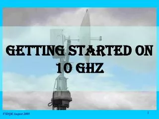
10 GHz Flyswatter Antenna Experiment Craig S. Young, KA5BOU ka5bou@arrl.net WWW.NTMS.ORG
The Problem • No Room at the Inn! • And still missing 2304/3456 loop yagis • Feedline Loss at 10 GHz • I Don’t Climb • Want access to transverter WWW.NTMS.ORG
Potential Solutions • Roving • Great when the weather cooperates • Enhancements don’t always coincide with roving times • “Flyswatter” arrangement • Well documented by W1GHZ • MUD Paper • Website • Recent QST Article WWW.NTMS.ORG
Flyswatter? WWW.NTMS.ORG
Actually, a Periscope • An antenna configuration in which the transmitting antenna is oriented to produce a vertical radiation pattern, and a flat or off-axis parabolic reflector, mounted above the transmitting antenna, is used to direct the beam in a horizontal path toward the receiving antenna. Note: A periscope antenna facilitates increased terrain clearance without long transmission lines, while permitting the active equipment to be located at or near ground level for ease of maintenance. WWW.NTMS.ORG
Performance Analysis • Estimated performance at 10 GHz • Courtesy W1GHZ Excel Spreadsheet WWW.NTMS.ORG
1 ¼” Angle Iron ¾” Angle Iron 32” System Design – Top Reflector • Designed to mount to Rohn 55 Tower (17” leg center-to-center) • Includes rung hooks for easier installation • Clamps to tower legs WWW.NTMS.ORG
Fly Swatter on the Ground WWW.NTMS.ORG
32” System Design- Dish Mount WWW.NTMS.ORG
Dish Mount on the Ground WWW.NTMS.ORG
Elevation Control • Used a TVRO actuator for control with a Winegard DM-4000 for feedback. • Actuator uses 12VDC – polarity changes direction • Integrated Az rotor controller and Elev control into single chassis with room to add future polarization controller WWW.NTMS.ORG
Flyswatter Controller WWW.NTMS.ORG
Complete System WWW.NTMS.ORG
“First Light” • NT5NT Beacon WWW.NTMS.ORG
Recent Activity – Aug UHF Contest • Of course, there were only 2 10GHz entries from NTX • KA5BOU • NM5M • Both with same 10 GHz score! • Congrats, Eric! WWW.NTMS.ORG
Recent Activity – Jan VHF Contest • Worked W5LUA and WW2R Direct • Once we found each other in frequency! • 3 and 6.4 miles, respectively • Worked NM5M and WA5VJB via rainscatter • 16.5 and 40 miles, respectively, via direct path • However, was working off storm near Red River • Approx 100 mile path to Eric • Approx 120 mile path to Kent WWW.NTMS.ORG
Azimuth Elevation Polarization Issues • In traditional dish installation for terrestrial work, elevation and polarization are fixed • More Degrees of Freedom! • Azimuth • Elevation • Polarization • Frequency WWW.NTMS.ORG
Issues • Alignment – Base to Reflector • Pointing Resolution • Elevation • Polarization WWW.NTMS.ORG
Alignment(base to reflector) • “1001 uses for a laser pointer” • #907 – use it to find the center of the dish mount relative to the center of the flyswatter • Mark cross-hairs on base WWW.NTMS.ORG
Azimuth Pointing • Resolution of current rotor controller is 6 degrees • However, every time I “tap” the meter face, the needle moves +/- 6-12 degrees! • Currently, I “get it close” with the meter and then fine-tune visually against the yagi-array WWW.NTMS.ORG
Azimuth Pointing WWW.NTMS.ORG
Elevation Issues • Winegard unit appears to be not 1:1 • I set it such that 45 degrees on readout is 45 degrees actual elevation using protractor/level – resulting in zero degree elevation of beam (at the horizon) • However, flat down (storage position for least wind load) is 9 degrees on the readout • Highest elevation reads 63 degrees, but is actually closer to 70 (didn’t measure) • May be where I have sensor mounted relative to flyswatter pivot point WWW.NTMS.ORG
50º 70º 45º 0º Elevation Issues (cont’d) • One degree of flyswatter tilt = 2 degrees of beam tilt! Beam=2(Elev) - 90 WWW.NTMS.ORG
Elevation Issues (cont’d) • Higher flyswatter tilt = loss from spillover WWW.NTMS.ORG
Polarization • Either dish or feed must rotate with flyswatter to maintain correct polarization WWW.NTMS.ORG
Polarization • 180 degrees of swing required on dish-end to maintain correct polarization • Must be synchronized to flyswatter • Current polarization control via “armstrong” method Angles in this half have equivalent polarizations in opposing half WWW.NTMS.ORG
Next Steps • Sun Noise Measurement? • Experiment with Other Bands • Permanent Dish Mount with Radome • Finer Resolution Az Control • Another 10ft? WWW.NTMS.ORG
Sun Noise? • What is lowest elevation for good sun noise measurement? • Given current geometry and assuming max flyswatter can be rotated in elevation is 65º, highest beam can be steered is 40º • Is this high enough? WWW.NTMS.ORG
5760 Analysis 50’ run of LMR-600 would have approx 3.6dB loss WWW.NTMS.ORG
3456 Analysis My current plan for this band is a 12’ Directive Systems loop yagi (25.2 dB) at tower top (61’). Assuming 70 ft. of LMR-600 (~5dB/100’), total system gain would be 21.7 dB WWW.NTMS.ORG
24 GHz Analysis With 2 ft dish With 1 ft dish WWW.NTMS.ORG
Dish with Radome WWW.NTMS.ORG
Finer Az Resolution(and polarization sync) • AA5C had great article in recent QST on fine azimuth control for 24 GHz • My plan is to take a similar approach for both flyswatter azimuth control and polarization control • Controlled via BASIC Stamp Microcontroller • Will allow synchronization of polarization with flyswatter azimuth • Will calculate and display actual elevation as well WWW.NTMS.ORG
10 more feet? • The KA5BOU “Bowl” WWW.NTMS.ORG
Questions? WWW.NTMS.ORG