Download
1 / 32
320 likes | 475 Views
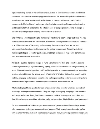
Evolution of Digital conception. Summary. How it was in the Past ? Conception : The UART case VHDL and reusability Future methods for making digital circuits Conclusion. In the PAST. Few years ago digital circuits were: With few functionalities =>Not very complex

E N D
Summary • How it was in the Past ? • Conception : The UART case • VHDL and reusability • Future methods for making digital circuits • Conclusion
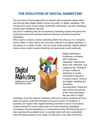
In the PAST • Few years ago digital circuits were: • With few functionalities =>Not very complex • Small in number of gates • The global function had to be divided in very elementary functions. Global function Fct 1 Fct 2 divided Fct 3 Fct 4 Fct 5
In the PAST • Few years ago digital circuits were: • With few functionalities =>Not very complex • Small in number of gates • The global function had to be divided in very elementary functions. Global function Fct 1 Fct 2 divided Fct 3 Fct 4 Fct 5
In the PAST • Steps of conception: • Truth tables: outputs versus inputs • Equations for each outputs • Simplification (different possibilities)
In the PAST • Steps of conception: • Components choice • Schematic • Place and route
In the PAST • Use of elementary Logic gates from different chips Example of a 4bits Adder with Carry-In, Carry-Out The 7400 chip contains 4 NANDs
In the PAST • Why this method can’t be used to create huge and complex digital circuits ? • Takes too much place on a board • Difficulty of reuse: • Very elementary functions • Totally dependant of the hardware choice (components) • 1 modification => do everything again.
Implementation of the UART • UART = The Universal Asynchronous Receiver Transmitter • Full duplex communication • Conversion of transmitted bits from parallel to serial, and vice versa in reception
Frame format • Convention: little endian • Least significant bit (LSB) first • Start bit to synchronize • 7 or 8 data bits • Parity bit to detect errors (odd/even) • Stop bit to provide a delay • There are the different configurations
Synchronisation • TRANSMITTER sends the data in an random time interval • RECEIVER has to recognize the start bit to synchronize itself • Best data sampling point
Chronogram (transmitter) • Tx_we = ‘1’ transmission
Chronograms (receiver) • Communication without error • Communication with error
Creation • Transmitter Finite state machine • Receiver Finite state machine • Baud rate generator flow chart • The receiver’s generator has one more input to be able to synchronize with the transmitter
Baud rate generator II • Calculation of the different speeds • Simulation
NOW: Challenge of Design Reuse • The solutions to create complex circuit: • Cycle of conception: • Language with high level of description TheVHDL • Hardware: • Use of programmable Integrated Circuits FPGA (Field Programmable Gate Array)
NOW: Challenge of Design Reuse • HDL Designer : state editor • Easier to read and update
NOW: Challenge of Design Reuse • HDL Designer • Accelerates Reuse • Create a quality VHDL code (support FPGA and RMM rules) • Visualize behavior and structure • Produces documentation automatically
Catapult C (1/2) • New C Design Flow • Unique Design Root • Top to bottom design oriented • Unified tool
CatapultC (2/2) • The adder’s case : CatapultC untimed C code : void adder(void) {int A,B,C; } A = B + C;
Modifications made simple • Multiple “targets” at once • The “One man” modification concept
Synthesis made simple 1/2 • Example : a Finite Impulse Response Filter
Synthesis made simple 2/2 • Outputs human readable VHDL code3500 linesin 10 seconds and …
Testing made simple • Exhaustive test benches • Direct comparison
Catapult C and beyond • Increased Specification to Market rate • Bundled Tool • Helps to find the best solution
Conclusion (1/2) • VHDL, VHDL Designer and Catapult permit: • To do more complex circuits • To reduce de conception time
Conclusion (2/2) Thanks for coming and listening ! Please feel free to ask any question.