Download
1 / 27
270 likes | 515 Views
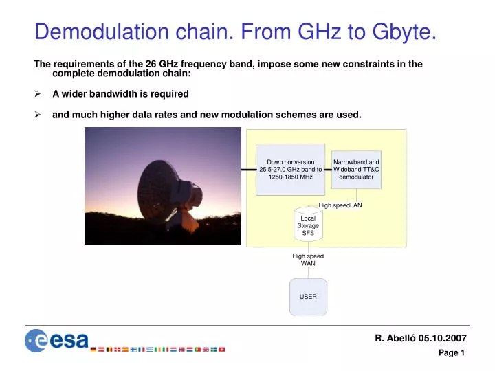
Demodulation chain. From GHz to Gbyte. The requirements of the 26 GHz frequency band, impose some new constraints in the complete demodulation chain: A wider bandwidth is required and much higher data rates and new modulation schemes are used. Down conversion (1 of 5).

E N D
Demodulation chain. From GHz to Gbyte. The requirements of the 26 GHz frequency band, impose some new constraints in the complete demodulation chain: • A wider bandwidth is required • and much higher data rates and new modulation schemes are used.
Down conversion (1 of 5) The critical requirements were: • IF Centre Frequency and Bandwidth. IF bandwidth large due to the very high data rate signals up to 400 Mbps. Two possibilities: • ~ 720 MHz (400 MHz bandwidth) • ~ 1500 MHz (600 MHz bandwidth). • Spurious Output: • Input RF bandwidth of 1.5 GHz and the large IF bandwidth , make difficult to control intermodulation products by means of filters. • Group Delay Variation: • Group delay variations greater than 10%→significant data degradation in OQSPK and GMSK. • is produced in filters, necessary to control spurious products. • Phase Noise: • The level of phase noise generated on a LO is related to the square of the LO frequency. To translate the RF input from K band to an IF at L band, the use of high frequency LOs is unavoidable. With the former requirements in mind, two different downconversion schemes were selected:
Down conversion (2 of 5) Frequency plan for the first proposed design
Down conversion (3 of 5) Frequency plan for the second proposed design
Down conversion (4 of 5) Trade-off of two frequency plans
Down conversion (5 of 5) DOWN CONVERTER CONCLUSION The final IF centre frequency was selected to be 1550 MHz with a bandwidth of 600 MHz. • A first frequency plan identified: first LO ~18.8 GHz and a tuneable 2nd LO centred at 5.9 GHz with an alternative frequency plan with first LO centred at 14.95 GHz. The required filters were selected from COTS suppliers and the characteristics of each filter were determined. The group delay variation, gain, noise figure and phase noise showed that using COTs components it is feasible to produce the required down converter. • Group delay variation is higher than the target specifications. It could be improved by selection of bespoke filters minimising the group delay response. Another alternative is to consider the use of group delay equalisation techniques in the demodulator. • Phase noise spectrum is marginal in a couple of spectral points. But the integrated phase noise is well below the standard specification.
Demodulator (1 of 14) IF FREQUENCY & Bandwidth To cover the full range of IFs, and cope with the present IFMS functionalities, while adding the requirements in the 26 GHz band, 3 different IF and sampling schemes were proposed: • Narrow band mode, the present reception of the IFMS (compatible with present stations)- 56 MHz to 84 MHz. • Medium band mode, the present reception in the stations (without L-band to 70 MHz downconverter) - 420 MHz to 640 MHz • S band to L band- 420 MHz to 520 MHz (spectrum inversion) • X band to L band- 540 MHz to 640 MHz (spectrum inversion) • Ka band to L band- 420 MHz to 620 MHz (direct) • Wide band mode, with the requirements on the 26 GHz band- 1250 MHz to 1850 MHz
Demodulator (2 of 14) IF FREQUENCY AND SAMPLING SCHEME The IF frequency that can be used in the high rate modem is constrained by theory: • (1) Nyquist’s sampling criterion and if subsampling the need to avoid spectral overlap after sampling. • And by technology : • (2) The availability of ADCs that can support the analogue bandwidth and sampling rate with adequate fidelity (ENOB, aperture jitter and SFDR). • (3) The Maximum Sampling rate of today’s (FPGA) technology. • (4) Sufficiently wide transition band so that an anti alias filter with sufficient stop band attenuation can be provided before the ADC.
Demodulator (3 of 14) Candidate sampling schemes for Wide band mode
Demodulator (4 of 14) Narrow Band Sampling Scheme Proposal to retain high sampling rate used in wide band mode: • Better spurious performance • Quantising noise spread out over wider bandwidth (so lower density) • Identical hardware as wide band mode • Reduced sampling clock phase noise constraints as sampling rate increased (phase noise tolerance proportional to sampling clock frequency)
Demodulator (5 of 14) Medium Band IF of 420 – 640 MHz sampling scheme • To suppress the L band to 70 MHz downconversion stage, the demodulator tuning range would need to be 420 to 640 MHz. • The same sampling as in Wideband mode (2.2 GHz) could be used, but a significant spurious tone is at 550 MHz (the clock used by the FPGAs). • Alternatively the medium band sampling rate could be changed to around 1.6 GHz (for all narrow band IFs) which would allow tuning the IF centre frequency over the full 420 – 640 MHz range without the ¼ sampling spurious falling into the pass band.
Demodulator (6 of 14) • The cleanliness of the received spectrum, required in Narrow band mode, was simulated with a real ADC, including dither.
Demodulator (8 of 14) DEMODULATOR ARCHITECTURE (1 of 2) Key features of the proposed demodulator architecture are: • Same sampling scheme for narrow, medium and wide band modes. Common analogue part. • Minimising the number of boards (target one board for the demodulator and one for a test modulator). This minimises the difficulty of interconnecting high speed signals. • Using the highly integrated devices to enable logic that would in the earlier generation of demodulator require a board, to fit in a single device. • Reprogramming of FPGAs “personality” to allow the same hardware to perform different functions when the operating mode is changed. • Use of existing IP from various sources: • the use of IP blocks from the FPGA manufacturer to perform standard functions • the reuse of IFMS IP for narrow band functions. • the use of exiting IP for standard DSP functions from external IP core sources.
Demodulator (9 of 14) Narrow band demodulator
Demodulator (11 of 14) Wide band demodulator
Demodulator (13 of 14) Hardware Architecture The proposed Hardware Architecture consists of 3 FPGAs Virtex-5 devices, Flash memory, additional RAM, and peripheral chips (Ethernet line driver etc). FPGA assignments are shown below.
Demodulator (14 of 14) DEMODULATOR CONCLUSION • The High rate Demodulator could be implemented on a single board with the digital signal processing performed in 2 Xilinx Virtex-5 FPGAs. • 2 high speed ADCs (one for LHCP and one for RHCP) are used, sub sampling the wide-band IF with a sampling rate of 2.2 GHz. • In Narrow band mode this high sampling rate is retained to give improved spurious performance. • Much of the IP (in particular the algorithms) developed for the IFMS could be reused in the Narrow Band mode. Other third party IP could be used such as Viterbi Decoders, Reed Solomon decoders and Turbo decoders. • The most challenging parts of the demodulator development are : • the high speed front end sampling at 2200 MHz • and the need to processes 2 complex samples in parallel.
Communication aspects (1 of 7) Due to the higher data rate (up to 400 Mb/s) and to the existing limitations in the maximum data rate that can be sent from the ground station to the control centre it is required to perform a feasibility activity to analyse the available Gigabit networks and to find the best communications configuration. The first task is to assess the desired traffic profiles (for all foreseen missions): • traffic type (stream vs. files) • peak and average throughput (taking into account pass duration) • maximum delivery time depending on current mission phase • desired QoS and redundancy/back-up The networking requirements must be derived from this information.
Communication aspects (4 of 7) Gigabit Network solutions for Cebreros to Darmstadt. In Cebreros, ESOC currently uses Telefonica. Telefonica is able to provide an end to end connection between Cebreros and Darmstadt, with bandwidths 155Mb/s, 622 Mb/s, or 2Gb/s. As an example, approximate costs (depending on the location) for a 155Mb/s connections from Madrid to Germany are: • Installation: from 7000 to 20000 euros • Monthly: from 11000 to 22000 euros NASA/JPL is already installing a 155 Mbps connection between some of their stations and Goldstone.
Communication aspects (5 of 7) • Gigabit Network solutions for New Norcia to Darmstadt. • In New Norcia, ESOC currently uses Telstra . Telstra will subcontract Stratos that is able to provide an end to end connection between New Norcia and Darmstadt with the required bandwidth. • Telstra is proposing a fully managed end to end service between the ESA ground station in Australia and the Control Facility in Germany. The service will be made up of two fully diverse links, each of which will consist of a pair of 622M IPL’s on a specific cable system terminated at each end by Siemens SDH equipment and Netex HyperIP devices. • Telstra is proposing to provide the complete end to end service for $1.4M USD per month based on a 3 year commitment term. This includes the Netex HyperIP equipment, Siemens SDH equipment, 4x622M International private lines and full 24x7 management including any links required for management purposes.
Communication aspects (7 of 7) • Store & Forward SFS hardware storage and network capabilities: • Data storage: RAID 5 system with minimum 2 TB (for 1 TM) or 6 TB (for 3 TM) • Network connections: 4 interfaces: • RG collection: 1 Gbps • TM collection: 1 Gbps • WAN with ESOC: 1 Gbps • M&C: 10 or 100 Mb/s A likely candidate for the S&F system was identified, with 24 TB storage. Main presentation