Download
1 / 45
530 likes | 912 Views
Learn about the differences between GMAW and FCAW welding processes, equipment used, safety precautions, advantages, disadvantages, and metal transfer methods.

E N D
Gas Metal Arc Welding (GMAW) Flux Cored Arc Welding (FCAW) (MIG) metal inert gas - incorrect because not always inert gases used (MAG) - metal active gas
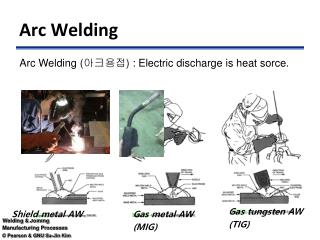
An electric arc between a continuously fed metal electrode and the base metal produces heat. The arc is shielded by a gas.
Popularity: • low cost used on all commercially important metals such as al, magnesium, stainless, carbon, alloys steels, copper etc.
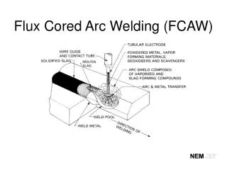
FCAW main difference from GMAW - • electrode is hollow • shielding gas is created from the flux inside the tubular electrode as it melts • also used to add alloying elements • some FCAW still requires additional shielding gas to be supplied • those that don't - called shelf shielding electrodes
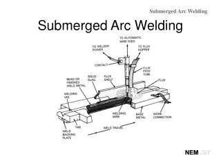
Equipment: • a constant voltage DC welder is used with this process shielding gases (carbon dioxide, argon, helium)metal electrode wireelectrode feed devicecable to carry: wire, current and shielding gas to the arctorch
SAFETY - same as for SMAW with addition of gas cylinder safety: • cap should be on cylinder when being moved or storedcylinders should be chained or secured to rigid object - wall etc.don't strike arc on cylinderstore and use in upright position
Advantages of GMAW and FCAW: • 1. continuous electrode - no stopping to change electrodes2. no electrode stub loss3. each pound of wire used, 92-98% becomes deposited weld metal (SMAW 60-70%)4. no slag, just a very thin glass like coating over the weld bead 5. deeper penetration possible than with SMAW6. less training and skill required
Disadvantages: • 1. equipment costs more than SMAW2. some joints hard to reach with welding gun3. rapid air movement (strong wind) can blow shielding gas away from weld
Two adjustments are made on the welding machine by the operator • 1. voltage2. wire feed speed • arc length,current, transfer method, and shielding gas are determined by the setting of these two parameters
Metal transfer occurs in two ways • 1.short circuiting method (short arc)2 metal transfer across the arc which includes: • a. globular b. spray
1. Short circuit transfer: • electrode touches molten pool, arc is no longer present, surface tension of pool pulls molten metal on the end of the electrode into the pool.repeats itself 100’s of times per second
Characteristics of Short Circuit • sounds like bacon frying • done with 100% CO2 or 75% CO2 and 25% argon • CO2 is a cold gas so get low heat input • minimizes distortion • for thin materials in all positions
2. Spray transfer • increase the current setting above the current required for short circuit - - Very fine droplets of metal form and travel at high speed directly through the arc stream to the weld pool.(100's of droplets per second)
Characteristics of spray • hotter - higher voltage arc • makes a hissing sound • it’s fast, pours the metal down - used in production • it is wet and hot - not good for out of position welds • for 1/8” and thicker material • must be 80% Argon or more for spray to occur -
There is an additional type of transfer called globular transfer • occurs at a point between short circuit and spray • metal transfers across the arc as large irregularly shaped drops
Continued: • does not occur in U.S. because we can get Argon gas relatively expensive • about 6X more expensive than CO2 • but in other countries, Argon is too expensive to use so they use CO2 and increase the weld current above that for short circuit
New technique called pulse • used to reduce fumes in production areas • sounds like a buzzing or humming when used properly
GMAW power sources: • AC generator or alternator with a DC rectifier • AC transformer with a DC rectifier
DCEP most common • DCEN seldom used - is used with only one electrode called an emissive electrode • welding machine tries to maintain a CONSTANT VOLTAGE during welding while current varies widely • AC is never used
Selecting electrode wire determined by: • 1. base metal2. shielding gas3. metal transfer method4. welding position • electrodes designed for all positions are designated as (E71T-X) • #1 indicates all positions
wire diameters: .030" to .0625" (1/16") • large dia. wire - not used for out of position welds • soft electrodes like al. and magnesium with small dia cannot be pushed through cable easily, must use push pull wire feeder - also use a Teflon liner.
Wire (electrode) Drive Unit • Wire drive unit: pulls electrode from spool and pushes it to welding gun • two mated rollers are located in the wire drive unit. • one roller is driven by a electric motor
Drive unit continued: • Amount of pressure - only enough to advance the wire without the rollers slipping. • Too much force could flatten soft wire or crush flux cored wire. • alignment of the wire guidesalignment of the drive rolls
Cleaning electrode cable • can use graphite powder in cable as lubrication
Shielding gasses: • inert: Argon (Ar)(most common), Helium (He)reactive: Nitrogen (N2), Oxygen (O2), carbon dioxide (CO2) they will mix with other chemicals such as the metal in the weld joint • reactive gasses gases are not used alone as shielding gases with exception of CO2
Gas selection consider: • 1. type and thickness of base metal welded • 2. amount of penetration2. metal transfer method to be used • 3. welding speed
Shielding gas flow rates: • see table 13-31 for suggested flow rates • too little gas flow = weld is not protected - will have a popping sound, spatter will occur, weld will have porosity
Shielding Gasses Cont. • heavier shielding gases like CO2 and Argon will tend to drop away from the weld area when welding out of position so the rate must be increased • may use a gas mixer or gasses can come premixed • each shielding gas has a different effect on shape of the bead and penetration
Gas nozzles and contact tubes: • gas nozzle - usually made of copper - come in various shapes and sizes • electrode contact tube (inside gas nozzle) - made in many diameters for wire • must fit tight enough to make a good sliding contact with electrode
Gas Nozzles Cont. • gas nozzle and contact tube should be about EVEN end of torch • gas nozzle becomes spattered, the flow of shielding gas will becomes turbulent • causes contamination • use a cleaning reamer or anti-stick compounds
Preparing metal surface: mechanically or chemically • groove angle for GMAW (30-45 deg) can be smaller than for SMAW (60-75 deg) (for of two reasons):1. wire dia are smaller2. GMAW penetrates better than SMAW
Electrode Extension: • amount the end of the electrode wire sticks out beyond the end of the contact tube. • maintain 1/4” to 1/2” extension for short circuit transfer method • too much extension = increase in resistance and cause current to heat along the extended wire - causes spatter, shallow penetration and low weld bead shape
Welding speed • determined by bead width and penetration
Torch angle • 1. Use forehand torch position about 15 deg away from direction of travel
To start the arc, wire and gas, squeeze the trigger - no striking is necessary as in SMAW • as the arc pool reaches the proper width, welder moves electrode forward
Torch Motion • For MIG, don’t use whipping motion - moves out of weld pool
If welding without a runoff tab, the welder can move the electrode to the end of the weld then back over the completed bead about 1/2" to fill the crater
Glass like slag is produced from MIG • can be cleaned with a wire brush
WHISKERS: • lengths of electrode wire stick through the root side of a groove weld • electrode wire is advancing ahead of the weld pool • to fix reduce the wire feed or slow the welding speed
Automatic and semiautomatic GMAW and FCAW: • semi - when operator holds and moves the gun and the electrode wire fed automaticallyfull automatic: when the gun is moved by a machine or robot
GMAW SPOT welding: • done on metals under 1/16"machine must be equipped with special controls