Download
1 / 34
340 likes | 499 Views
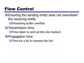
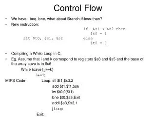
Flow Control. Overview. Open Loop flow control No feedback, traffic shaping Closed Loop control Feedback used to do source to destination control. Absolute peak control Allocating peak bandwidth for each channel. No statistical multiplexing possible. Violation Tagging. violation tagging

E N D
Overview • Open Loop flow control • No feedback, traffic shaping • Closed Loop control • Feedback used to do source to destination control. • Absolute peak control • Allocating peak bandwidth for each channel. No statistical multiplexing possible
Violation Tagging • violation tagging • Cells are divided between high priority and best effort, over contract cells. • Example- voice, divide 4 MSB into non-tagged stream, 4 LSB tagged stream • High priority video frames sent in own stream. • Open loop scheme since no feedback is required
Congestion • Congestion • Delays increase rapidly • Buffers overflow • Cells are dropped • Throughput drops • Deadlock
Congestion Control • Recognize congestion early before cells are dropped • Send signal to source • Source invokes control
Recognizing Congestion • Average queue length threshold • TCP uses timeout • Global queue occupancy?
Congestion Indication • Forward Explicit Congestion Notification FECN bit in Payload type field • Set in packet to destination • Backward Explicit Congestion Notification BECN • Set in packet in reverse direction, to source
Invoking Control • Window Control • Specifies a limit on the number of unacknowledged segments • Window size can be lowered on congestion • Rate Control • Leaky bucket rate varied by congestion information (RM cells) • Credit based control • Source limited to a specified number of cells before waiting for more credits
m m m Window Control Model 1 2 M W Round Trip Delay
Window based control • Congestion recognized by queue thresholds • W=dW exponential reduction Q(q) > L • d < 1 • W=W+b linear increase Q(q) < L
Explicit Binary Feedback • Ramakrishnan and Jain • Similar to FECN • Set bit in acknowledgment if congestion in switch • If 50% of acks have bit set W=.875W • Otherwise W = W+1 • Internet uses W=.5W
Power Function delay Max Power Throughput
Maximizing Power • Power = throughput/delay • for M/D/1
Queue Length Packets passing through switch will be set 50% of the time
Rule • Use rule that if 50% of bits are set, reduce rate
Oscillations • methods proposed to dampen oscillations • Base action on average queue level, not current level • Reduce window size at a smaller rate
Rate Based ATM Forum • EPRCA • Enhanced Proportional Control Algorithm • rate based chosen over credit based approaches • Credit based requires Per VC queuing • Link by link flow control
EPRCA • VC transmits at Allowed Cell Rate (ACR) • Rate is reduced by ADR after each cell • Every Nrm cells, generate RM cell in backward direction • When received from Destination, increment rate by Nrm*ADR • Rate is reduced if RM cell is lost
RM Cells • RM Cell • Resource Management Cell • PT=110 • Backward or forward indication • Congestion Indication set by destination if EFCI bit is set • Explicit Cell Rate ER, Minimum Cell Rate MCR, Current Cell Rate CCR, Allowable Cell Rate ACR, Initial Cell Rate ICR
PT Field • 000 User Data, no Congestion, SDU 0 • 001 End of AAL5 packet • 010 User Data, Congestion, no end • 100 Segment OAM flow • 101 End to End OAM • 110 RM Cell • 111 Reserved
Simulation Varying Lengths Switch Switch
Parameters • 1 to 50 Km link length • 50 and 1000Km backbone length • PCR=300000, ICR=PCR/20, MCR=PCR/1000, ADR=ACR/256 • Stable oscillations 8-9msec, 850-900 cell buffers
m m m Heavy Traffic Case M Switches 1 2 M W Round Trip Delay
Asymptotic Performance Heavy Usage (congested) R Increasing W 1 Moderate Usage Optimal W G/g 1
Analysis • Power = throughput/delay (g/R) • Maximized at knee of curve • Little additional throughput results from increasing window size • optimal Window size
Example • a) 2.4Gbps, 1000Km path, 10 switches • G=28000 cells • b) 45Mbps, 1000Km path, 10 switches • G=530 cells
Rule of thumb • set W to G
Queueing delay • queuing delay or SOL delay • For high bandwidth connections, SOL • If power is maximized queuing delays dominate • What about LANs? • Longer packet lengths, smaller bandwidth • queuing delays dominate
Other Conclusions • Where are most of the cells in the network? Are they in buffers, or on the communication links? • Most of the cells are on the links in high bandwidth-delay networks
Mitra’a algorithm • Stay at maximum power point • As throughput increases, decrease window size • Maintain equations
Delayed-feedback, rate-control • Unstable equilibrium point • queue length q= • oscillation period O(t) • fluxuations bounded by • throughput within • response time at most