Download
1 / 12
120 likes | 323 Views
6. Transmittance Functions, Lenses, and Gratings. 6.1 Tilt. transmittance function. 1 function[uout]=tilt(uin,L,lambda,alpha,theta) 2 % tilt phasefront 3 % uniform sampling assumed 4 % uin - input field 5 % L - side length 6 % lambda - wavelength 7 % alpha - tilt angle

E N D
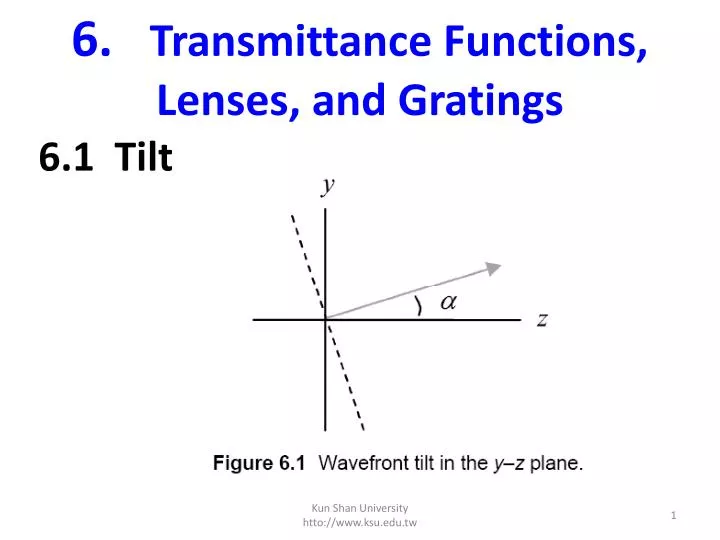
6.Transmittance Functions,Lenses, and Gratings 6.1 Tilt Kun Shan University htto://www.ksu.edu.tw
transmittance function 1 function[uout]=tilt(uin,L,lambda,alpha,theta) 2 % tilt phasefront 3 % uniform sampling assumed 4 % uin - input field 5 % L - side length 6 % lambda - wavelength 7 % alpha - tilt angle 8 % theta - rotation angle (x axis 0) Kun Shan University htto://www.ksu.edu.tw
9 % uout - output field 10 11 [M,N]=size(uin); %get input field array size 12 dx=L/M; %sample interval 13 k=2*pi/lambda; %wavenumber 14 15 x=-L/2:dx:L/2-dx; %coords 16 [X,Y]=meshgrid(x,x); 17 18 uout=uin.*exp(j*k*(X*cos(theta)+Y*sin(theta))... 19 *tan(alpha)); %apply tilt 20 end Kun Shan University htto://www.ksu.edu.tw
6.2 Focus transmittance function for focus Kun Shan University htto://www.ksu.edu.tw
1 function[uout]=focus(uin,L,lambda,zf) 2 % converging or diverging phase-front 3 % uniform sampling assumed 4 % uin - input field 5 % L - side length 6 % lambda - wavelength 7 % zf - focal distance (+ converge, - diverge) 8 % uout - output field 9 10 [M,N]=size(uin); %get input field array size 11 dx=L/M; %sample interval 12 k=2*pi/lambda; %wavenumber 13 % 14 x=-L/2:dx:L/2-dx; %coords 15 [X,Y]=meshgrid(x,x); 16 17 uout=uin.*exp(-j*k/(2*zf)*(X.^2+Y.^2)); %apply focus 18 end Kun Shan University htto://www.ksu.edu.tw
sqr_beam_focus Thefollowing before the propagation call and run the script: zf=2000; [u1]=focus(u1,L1,lambda,zf); Kun Shan University htto://www.ksu.edu.tw
6.3 Lens • A lens is an optical element that uses refraction to focus or diverge light. Thetransmittance function for an ideal, simple lens is given by where f is known as the focal length and P(x,y) is the pupil function Kun Shan University htto://www.ksu.edu.tw
However, all is not lost for smaller f/#s. If the field incident on the lens isU1(x1, y1), then the field exiting the lens is U1(x1, y1)tA(x1, y1). • Insert this into Eq.(4.25) for U1(x1, y1) and set z = f. • The chirp functions in the integral cancel, andthe result is Kun Shan University htto://www.ksu.edu.tw
The expression in Eq. (6.18) shows the field at the focal plane of an idealpositive lens is simply the Fraunhofer pattern of the incident field with z = f. • Therefore, to find the field or irradiance pattern in the focal plane of apositive lens • including one with a small f/#, the function “prop_FF” from theprevious chapter can be applied replacing z with f. Kun Shan University htto://www.ksu.edu.tw
Take the parameters from the f/10 lens example and assume U1 is a unitamplitude plane wave. • Select M = 250 and L = 250 mm. The irradiance pattern inFig. 6.7 is generated for the focal plane using prop_FF (see Exercise 6.4). Try it! • The focused irradiance pattern formed with an ideal circular-shaped lens, such asshown in Fig. 6.7, is known as the Airy pattern. Kun Shan University htto://www.ksu.edu.tw