Download
1 / 34
340 likes | 364 Views
Explore architectural and interaction models in distributed systems, including middleware's role in masking heterogeneity for convenient programming. Learn about socket-based communication, protocol layering, and interaction models in network APIs.

E N D
System Models Chapter 2: Coulouris + Chapter notes from K. Birman’s that in turn was based on Professor Paul Francis, Cornell University
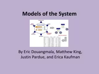
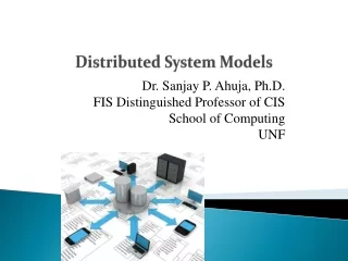
Distributed system models • Model: “a simplified representation of a system or phenomenon, as in the sciences or economics, with any hypotheses required to describe the system or explain the phenomenon, often mathematically.”
System Models • Architectural model defines the way in which the components of the system are placed and how they interact with one another and the way in which they are mapped onto the underlying network of computers. • Interaction model deals with communication details among the components and their timing and performance details. • Failure model gives specification of faults and defines reliable communication and correct processes. • Security model specifies possible threats and defines the concept of secure channels. • We will look at architectural models + Interaction models in this discussion; We will deal with failure and security models later in the semester.
Architectural Model • Concerned with placement of its parts and relationship among them. • Example: client-server model, peer-to-peer model • Abstracts the functions of the individual components. • Defines patterns for distribution of data and workload. • Defines patterns of communication among the components. • Example: Definition of server process, client process and peer process and protocols for communication among processes; definition client/server model and its variations.
Middleware • Layer of software whose purpose is to mask the heterogeneity and to provide a convenient programming model for application programmers. • Middleware supports such abstractions as remote method invocation, group communications, event notification, replication of shared data, real-time data streaming. • Examples: CORBA spec by OMG, Java RMI, grid software (Globus, Open grid Services), Web services.
Clients invoke individual servers EX: 1. File server, 2. Web crawler EX: Web server EX: browser, web client
A service provided by multiple servers EX: akamai, altavista, Sun’s NIS (data replication)
Web proxy server and caches Proxy servers + cache are used to provide increased Availability and performance. They also play a major role Firewall based security. http://www.interhack.net/pubs/fwfaq/
A distributed application based on peer processes Ex: distributed Whiteboard Application; Music sharing
Web applets EX: Code streaming; mobile code
Interaction Models • Within address space (using path as addresses) • Socket based communication: connection-oriented, connection-less • Socket is an end-point of communication • Lets look at some code + details
Socket based communication int sockfd; struct sockaddr_in addr; addr.sin_family = AF_INET; addr.sin_addr.s_addr = inet_addr(SERV_HOST_ADDR); addr.sin_port = htons(SERV_TCP_PORT); sockfd = socket(AF_INET, SOCK_STREAM, 0); connect(sockfd, (struct sockaddr *) &addr, sizeof(serv_addr)); do_stuff(stdin, sockfd);
Start with host name (maybe) Classic view of network API foo.bar.com
Start with host name Get an IP address Classic view of network API foo.bar.com gethostbyname() 10.5.4.3
Start with host name Get an IP address Make a socket (protocol, address) Classic view of network API foo.bar.com gethostbyname() 10.5.4.3 socket();connect();… sock_id
Start with host name Get an IP address Make a socket (protocol, address) Send byte stream (TCP) or packets (UDP) Classic view of network API foo.bar.com gethostbyname() 10.5.4.3 socket();connect();… sock_id … 1,2,3,4,5,6,7,8,9 . . . TCP sock UDP sock Network Eventually arrive in order May or may not arrive
Protocol layering • Communications stack consists of a set of services, each providing a service to the layer above, and using services of the layer below • Each service has a programming API, just like any software module • Each service has to convey information one or more peers across the network • This information is contained in a header • The headers are transmitted in the same order as the layered services
HTTP HTTP Router Link1 Link1 Link2 Link1 TCP TCP IP IP IP Protocol layering example Browser process Web server process Physical Link 1 Physical Link 2
Router Protocol layering example Browser wants to request a page. Calls HTTP with the web address (URL). HTTP’s job is to convey the URL to the web server. HTTP learns the IP address of the web server, adds its header, and calls TCP. Browser process Web server process HTTP HTTP H TCP TCP IP IP IP Link1 Link1 Link2 Link1 Physical Link 1 Physical Link 2
Router Protocol layering example TCP’s job is to work with server to make sure bytes arrive reliably and in order. TCP adds its header and calls IP. (Before that, TCP establishes a connection with its peer.) Browser process Web server process HTTP HTTP TCP TCP H T IP IP IP Link1 Link1 Link2 Link1 Physical Link 1 Physical Link 2
Router Protocol layering example IP’s job is to get the packet routed to the peer through zero or more routers. IP determines the next hop from the destination IP address. IP adds its header and calls the link layer (i.e. Ethernet) with the next hop address. Browser process Web server process HTTP HTTP TCP TCP IP IP IP H T I Link1 Link1 Link2 Link1 Physical Link 1 Physical Link 2
Router Protocol layering example The link’s job is to get the packet to the next physical box (here a router). It adds its header and sends the resulting packet over the “wire”. Browser process Web server process HTTP HTTP TCP TCP IP IP IP Link1 Link1 Link2 Link1 Physical Link 1 Physical Link 2 H T I L1
Router Protocol layering example The router’s link layer receives the packet, strips the link header, and hands the result to the IP forwarding process. Browser process Web server process HTTP HTTP TCP TCP IP IP IP H T I Link1 Link1 Link2 Link1 Physical Link 1 Physical Link 2
Router Protocol layering example The router’s IP forwarding process looks at the destination IP address, determines what the next hop is, and hands the packet to the appropriate link layer with the appropriate next hop link address. Browser process Web server process HTTP HTTP TCP TCP IP IP IP H T I Link1 Link1 Link2 Link1 Physical Link 1 Physical Link 2
Router Protocol layering example The packet goes over the link to the web server, after which each layer processes and strips its corresponding header. Browser process Web server process HTTP HTTP H TCP TCP H T IP IP IP H T I Link1 Link1 Link2 Link1 Physical Link 1 Physical Link 2 H T I L2
Basic elements of any protocol header • Demuxing field • Indicates which is the next higher layer (or process, or context, etc.) • Length field or header delimiter • For the header, optionally for the whole packet • Header format may be text (HTTP, SMTP (email)) or binary (IP, TCP, Ethernet)
Ethernet: Protocol Number Indicates IPv4, IPv6, (old: Appletalk, SNA, Decnet, etc.) IP: Protocol Number Indicates TCP, UDP, SCTP TCP and UDP: Port Number Well known ports indicate FTP, SMTP, HTTP, SIP, many others Dynamically negotiated ports indicate specific processes (for these and other protocols) HTTP: Host field Indicates “virtual web server” within a physical web server Demuxing fields
IP (Internet Protocol) • Three services: • Unicast: transmits a packet to a specific host • Multicast: transmits a packet to a group of hosts • Anycast: transmits a packet to one of a group of hosts (typically nearest) • Destination and source identified by the IP address (32 bits for IPv4, 128 bits for IPv6) • All services are unreliable • Packet may be dropped, duplicated, and received in a different order
IP(v4) address format • In binary, a 32-bit integer • In text, this: “128.52.7.243” • Each decimal digit represents 8 bits (0 – 255) • “Private” addresses are not globally unique: • Used behind NAT boxes • 10.0.0.0/8, 172.16.0.0/12, 192.168.0.0/16 • Multicast addresses start with 1110 as the first 4 bits (Class D address) • 224.0.0.0/4 • Unicast and anycast addresses come from the same space
UDP (User Datagram Protocol) • Runs above IP • Same unreliable service as IP • Packets can get lost anywhere: • Outgoing buffer at source • Router or link • Incoming buffer at destination • But adds port numbers • Used to identify “application layer” protocols or processes • Also a checksum, optional
TCP (Transmission Control Protocol) • Runs above IP • Port number and checksum like UDP • Service is in-order byte stream • Application does not absolutely know how the bytes are packaged in packets • Flow control and congestion control • Connection setup and teardown phases • Can be considerable delay between bytes in at source and bytes out at destination • Because of timeouts and retransmissions • Works only with unicast (not multicast or anycast)
UDP vs. TCP • UDP is more real-time • Packet is sent or dropped, but is not delayed • UDP has more of a “message” flavor • One packet = one message • But must add reliability mechanisms over it • TCP is great for transferring a file or a bunch of email, but kind-of frustrating for messaging • Interrupts to application don’t conform to message boundaries • No “Application Layer Framing” • TCP is vulnerable to DoS (Denial of Service) attacks, because initial packet consumes resources at the receiver
Summary • When designing systems or analyzing systems, you want to examine at the high level the architectural model. • Subsequent steps will explore functional models such as interaction model, security model, failure model, reliability model etc.