Download
1 / 16
310 likes | 594 Views
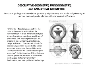
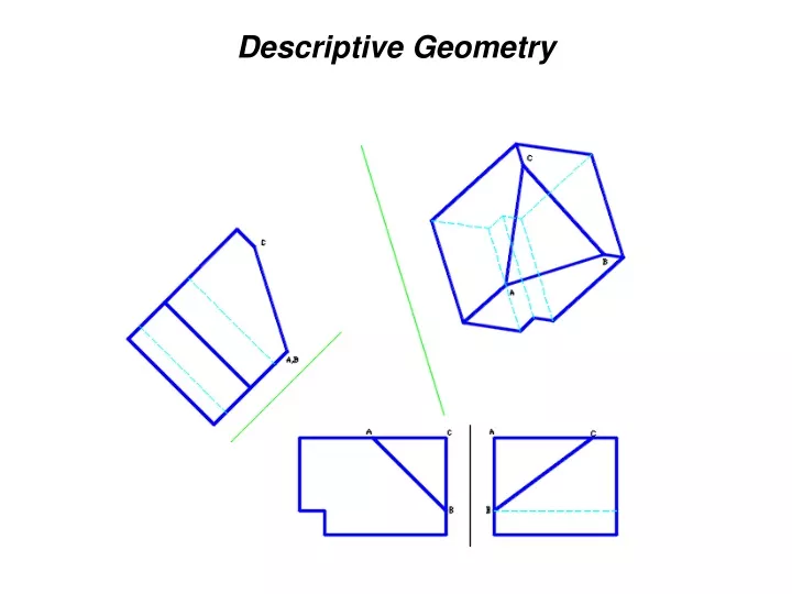
Descriptive Geometry. Descriptive Geometry. The projection of three-dimensional figures onto a two-dimensional plane of paper in a manner that allows geometric manipulations to determine lengths, angles, shapes, areas and other quantitative information by means of graphics.

E N D
Descriptive Geometry • The projection of three-dimensional figures onto a two-dimensional plane of paper in a manner that allows geometric manipulations to determine lengths, angles, shapes, areas and other quantitative information by means of graphics. • Based on orthographic projections • Auxiliary views are used to show true lengths and point views of lines, true size and edge views of planes, angles between two lines, between two planes and between a line and a plane. • The Folding-Line Model can be used to visualize auxiliary views.
Point • A location in space • No dimension • Needs three coordinates (x,y,z) to define location in space: height (below H), width (left of P), depth (behind F) • Needs at least two views to show coordinates
Lines • Straight path between two points • A line can appear as: • foreshortened line • true-length line (TL) • point
Lines • Principal Line - parallel to at least one principal projection planes (H,F, P) • Oblique Line - neither parallel nor perpendicular to any principal plane • Principal Lines: • horizontal - parallel to H; TL in top view • frontal - parallel to F; TL in front view • profile - parallel to P; TL in side views
True Length of a Line • Pythagorean Theorem • True length diagram • Auxiliary View of the line Pythagorean Theorem
True Length of a Line True Length Diagram
True Length of a Line: Auxiliary View • Line of sight needs to be perpendicular to the line • But line of sight is perpendicular to the reference (or projection plane) • Therefore, reference plane must be parallel to the line. The resulting view will show the TL of the line.
Direction of a Line • Shown in the Top View • Compass Bearing • Angle measured from the N or S • angle is between 0 and 90 degrees • Azimuth • Angle measured clockwise from the north • angle is between 0 and 360 degrees
Slope of a Line • Measure of steepness/inclination with horizontal • Can be specified using • a. Slope = rise/run • b. %grade = slope × 100% • c. Slope angle • Angle between the TL of the line and the horizontal plane (H). • Find TL off the TV. The resulting view will show the angle between the TL of the line and the horizontal plane (corresponding to the H-ARP fold line).
Point-View of a Line Procedure: • 1. Find the true length of the line • a. Take a reference plane parallel to the line • b. Project the endpoints perpendicular to the reference plane. Label all reference planes. • c. Transfer distance away from “previous” corresponding reference plane • 2. Take a reference plane perpendicular to TL. • 3. Project and transfer. Line should be Ptview.
Edge View of a Plane - Find the Pt. View of any line in the plane. Procedure: • 1. Find a line in the plane that is shown as a TL. A. Draw a horizontal line 1-0 on the plane in the front view. B. The line in step A is TL in the top view. The desired line of sight is parallel to the TL line. • 2. Take a reference plane perpendicular to the located TL. • 3. The point view of line 1-0 is found by projecting from the top view. Locate 1 by transferring the dimension H from the front view. • 4. Locate points 2 and 3 by transferring their height dimensions from the front view. The plane should be EV.