Download
1 / 48
480 likes | 640 Views
Transforming Technologies Presents. ALPHABOOST™ The Next Generation of Ultra-Clean Air Ionization. Outline. Microcontamination, Electrostatics and High Tech Manufacturing Corona Ionizers and their Contamination Mechanisms collide with the 25 nm node

E N D
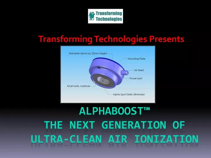
Transforming Technologies Presents ALPHABOOST™The Next Generation of Ultra-Clean Air Ionization
Outline • Microcontamination, Electrostatics and High Tech Manufacturing • Corona Ionizers and their Contamination Mechanisms collide with the 25nm node • Alphaboost® The Advantages of Corona without the Tradeoffs • Summary
Effects of Static Charge on High Technology Manufacturing
AParticleContaminationStudy Contamination Study 200 mm wafer in a Class 1 Mini-Environment Wafer at 0 V class 1 mini environment for 6 weeks Wafer at 2000 V class 1 mini environment for 6 weeks Data from Frank Curran, MS thesis, "The Effects of Static Charge on Silicon Wafers in the Semiconductor Industry," The Engineering Council of England, Nov. 1997
Electrostatic Attraction Defeated by Mini-Environment Ionizers “Implementing a Static Control Program to Increase the Efficiency of Wet Cleaning Tools” Micro Magazine June 2001. Long, CW, Peterman, J and Levit, L.B. http://www.micromagazine.com/archive/06/01/long.html
In 1990 Corona Ionization Was the State of the Art Corona Ion Bars were available with Sub Class 1 Cleanliness This was absolutely acceptable for semiconductor manufacturing Fed Std 209E Class 1 requires less than one 500 nm particle/cubic foot of fab air.
The CD Compared to 500 nm Particles CD circa 1990 500 nm 1995 2000 2005 2010 20 • Ionizer Performance can no longer be judged by Fed Std 209E. • Ionizer performance must be related to KILLER Particles!
Semiconductor Front End Processing 2009 ITRS Roadmap
Semiconductor Fab: What Particle Size Causes Yield Loss? For the present 45 nm node (DRAM 1st Level Metal ½ Pitch)* 45 nm Metal1 90 nm 45 nm Either of these contaminating particles can kill the die! Define killer particle size as a ≥ ½ * 45 nm for this 45 nm technology (allow for uneven pitch) * 2009 Intl. Technology Roadmap for Semiconductors Update, http://www.itrs.net/
How Small is 22 nm? 110 mm 60 mm 3 mm 100 nm 22 nm 2 nm
Corona Ionizers and their Contamination Mechanisms The invisible contaminant
Corona Ionizers Use Sharp Points to Generate an Intense Electric Field • In time the plasma at the tips erodes the points. • Where did the material go? • This erosion is the main source of large particles and you pay extra to get points that do not erode easily. • But they still erode. • Even silicon points must be replaced every two years due to erosion. Photograhs from http://www.ion.com/documents/technical/EmitterMaintenance.pdf
Beyond Erosion, All Corona Ionizers Turn AMC gasses into Solid Particles This is Called Agglomeration
Range of Agglomerated Particle Emissions from High Technology Air Ionizers Particles Per Cubic Foot Particle Size (Microns) Data based upon a survey or readily available published results. E.G. see www.simco.com, www.ion.com, www.desco.com, www.meech.com
Specifying a Corona Ionizer at 0.5 mm Made Sense in 1990 but NOT in 2011! Particles Per Cubic Foot Particle Size (Microns) Extrapolation based upon normalized 1/x3 distribution accepted by the industry
What is the Impact of These Tiny Particles? For Particles from the Cleanest Corona Ionizer… • Particle Density, r(r)=12 particles/ft3 @ 22.5 nm or greater • Laminar flow rate in Mini-environment, v= 60 ft/min • Wafer Residence Time in EFEM, t= 1 minute • The Number of Particles moving over a wafer : • Take d=300 mm, N=(12part/ft3)p(d/2)2vt= • 267 particles 22.5 nm or greater!
Particles from Ionizers are Charged so Most (~50%) Will Stick! • For a 45 nm process with 22.5 nm as a killer particle size, • Particle Load/wafer~2700/2=267 particles @22.5 nm orgreater. • Assume 2% actually kill a die. • Assume 500 die per wafer, 400 process steps. • Particle Limited Yield=98.67% • Particle Limited Yield (1000 die/wafer)=99.27%
What Happens at the 25 nm Node? • For a 25 nm process with 10 nm as a killer particle size, • Particle Load/wafer~2700/2=1350 particles. • Assume 2% actually kill a die. • Assume 500 die per wafer, 400 process steps. • Particle Limited Yield=94%! • Particle Limited Yield (1000 die/wafer)=96%! This yield loss cannot be tolerated!
Which do You Want? • Fab Contamination Particle Load • Ionizer Contamination Load? • Neither? We have found a way to allow neither! It’s Called AlphaBoost®
To Understand the Advantages of AlphaBoost®, Examine how these Particles are Made: • There are lots of organic vapors in a semiconductor cleanroom. Cyclohexasiloxane • These chemicals are “cooked” by corona ionizers.
25oC 100oC 500oC 750oC ANY Corona Ionizer in FabAir will be Effected by these AMCs. The corona process generates heat at the very tip of the emitter W=iV =5 mA*10kV =50 mW of heat The heat disassembles the AMCs into radicals and cooks the “soup”.
A Free Radical Soup in an Electric Field will Grow Particles! High Voltage On Point Creates Strong Electric Fields Particle is drawn in by dielectrophoretic force + - + - + - Particle picks up charge from emitter point Particle is repelled from emitter point
As the Tiny Particle Crosses the Plasma (Twice) it Picks up Free Radicals from the Soup
Agglomeration in the Macro World: Watch water droplets slide down the outside side of a cold glass of beer Hail Falling From the clouds
Maintenance of Corona Ionizers Dealing with the Fuzz Emitter points must be cleaned every few months and the ionizer must be rebalanced with a CPM
Summary: • Corona Ionizers ALL Make Sub Micron Particles • Most also make larger Particles • Corona Ionizers all Must be Cleaned and Re-Balanced every 1-3 months – this is expensive and time consuming. • AlphaBoost® Eliminates all of these Issues
AlphaBoost – the Advantages of Corona Without the Tradeoffs The invisible contaminant
Alpha Emitter Technology – the Engine in AlphaBoost® Alpha Technology Uses Alpha Technology Requires • No High Voltage (kV) • No Emitter Points • No Electrical Power • No Cleaning • No Adjusting
Alpha Emitter Technology Employs Po210, a 5.3 MeV Alpha Source • Alpha particles move up to 4 cm from the source and stop • They become Helium atoms and drift away harmlessly • As they Travel, each one makes ~250,000 ion Pairs` • No electricity is required to make ions • Ion output is automatically balanced with no adjustments.
The Alphas Collide with Air Atoms and Ionize Them ion ion ion ion ion ion ion ion ion ion The process continues as long as the source is active ((1-2 years)
Is the Alpha Source Safe? Yes! Safety Rules: • Alpha particles are stopped by • a sheet of paper • or by the dead skin covering your body • Once they stop, Alpha particles become harmless helium atoms • Don’t eat alpha sources • Don’t smoke alpha sources! • Return them after they are spent • They convert into lead
Ordinary Alpha Ionizers In Laminar Airflow may not Discharge an Entire EFEM ULPA No Ions Here! Ions Recombine Before they Reach the Target
Alphaboost™ Separates Ion Polarities and Push Ions down Electrostatically in Waves ±300 - 500 V Height of EFEM Half Cycle ~ Laminar Flow Velocity Ions move 1+ m!
The Product is Compact and Easy to Mount in an EFEM The ionizing element is the size of a coin
AlphaBoost Has • No KiloVolt voltages • No Need for Balance Adjustment • No Corona • No Sharp Points to Wear Out • No Fuzz Ball Creation Mechanism • No Gas to Particle Agglomeration Mechanism
Ionizer LPC Cleanliness Study * 94.2±4 particles/ft3 with ionizer ON and 95.5±3 particles/ft3 with ionizer OFF *Robert Wilson, ESDA Symposium 1987, A Novel Nuclear Ionization Source Employing a Pulsed Electric Field
Ionizer CNC Cleanliness Study * 1.25.2±0.9 particles/ft3 with ionizer ON and 3.3±0.15 particles/ft3 with ionizer OFF *Robert Wilson, ESDA Symposium 1987, A Novel Nuclear Ionization Source Employing a Pulsed Electric Field
Operation of AlphaBoost® in an EFEM ULPA 80 fpm air flow • Typical Discharge Performance 1 m below the ionizer : • Discharge times ± 25 seconds • Voltage Swing +15 V • Set to ±500 V Bias Swing • Frequency 2.0 Hz
Operation of AlphaBoost® Adjacent to a Wafer Aligner ULPA 80 fpm air flow • Typical Discharge Performance 25 cm below the ionizer : • Discharge times ± 7 seconds • Voltage Swing +5 V • Set to ±300V Bias Swing • Frequency 4.0 Hz 75 cm 25 cm
AlphaBoost® Benefits • Fast Discharge time • Balanced by Physics, not by Adjustment • Inherently Stable • No Fuzzball to Clean Off • No points to Replace • No CPM Balance Adjustment • Same Delivery Efficiency as Corona Technology
Conclusions • Records went from the phonograph cylinder to 78 RPM hard plastic to Vinyl High Fidelity Recordings and • Underwent Constant Improvement of the Same Technology • But they Eventually they Became Obsolete – limited life, sensitivity to handling & to dust • Cameras went from the pin-hole to lens to multi element lenses but it took digital photography to satisfy today’s photographers. • Corona Ionizers underwent Technology boosts • from Tungsten to Titanium to Silicon points and • from AC to DC to Pulsed DC to Complex Waveforms • But Technology has passed them by • Electricity was Generated by Burning Dirty Coal in 1900. Now Clean Solar Electrical Power is Coming on Line rapidly!
Semiconductors at the 25 nm Node and Beyond Require Alphaboost® to Fab Chips Cleanly and Economically