Download
1 / 15
180 likes | 498 Views
Alternating Current (AC) Circuits. AC Voltages and Phasors Resistors, Inductors and Capacitors in AC Circuits RLC Circuits Power and Resonance. AC Sources and Phasors. Consider a sinusoidal voltage source:. This source can be represented graphically as a vector called a phasor :. b. b.

E N D
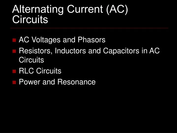
Alternating Current (AC) Circuits • AC Voltages and Phasors • Resistors, Inductors and Capacitors in AC Circuits • RLC Circuits • Power and Resonance
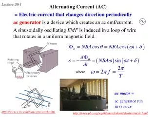
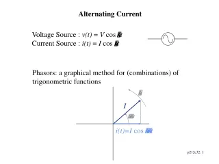
AC Sources and Phasors Consider a sinusoidal voltage source: This source can be represented graphically as a vector called a phasor: b b Vmax Vmax V(t) T a wt e c a,e c time -Vmax d d Great web page: http://www.phys.unsw.edu.au/%7Ejw/AC.html
Resistors in AC Circuits Since both have the same arguments in the sine term, iR and DvR are in line, they are in phase.
Announcements • Cell phones on silent • Check mid-term grades.
Inductors in AC Circuits Inductive Reactance For a sinusoidal voltage, the current in the inductor always lags the voltage across it by 90°.
Inductors in AC Circuits • Filter for woofer • Low frequencies pass through • High frequencies get blocked. VR Frequency Woofer
Capacitors in AC Circuits Capacitive Reactance For a sinusoidal voltage, the current in the capacitor always leads the voltage across it by 90°.
Inductors in AC Circuits • Filter for tweeter • High frequencies pass through • Low frequencies get blocked. VR Frequency Tweeters
Using Phasors in a RLC Circuit Impedance
Example 33.5 R = 425 W L = 1.25 H C = 3.5 mF w = 377 s-1 DVmax = 150 V
Power in an AC Circuit No power loss occurs in an ideal capacitor or inductor. For a purely resistive load, f=0
Resonance in Series RLC Circuits A circuit is in resonance when its current is maximum. Irms=max when XL-XC=0 Resonance Frequency Tuner for radio!
www.barlowwadley.it Inductor Variable Capacitors