Download
1 / 44
440 likes | 463 Views
This report discusses the study results of the Z-pole operation of ILC@250GeV, focusing on the undulator scheme for positron production. Various issues related to the operation are examined, including repetition rate, damping ring, main linac, and beam dynamics.

E N D
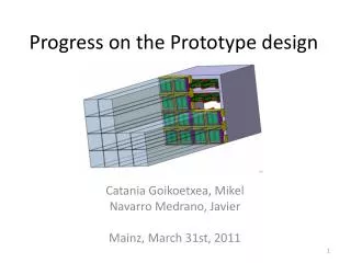
Progress in the Accelerator Design Operation at Z-pole Status of Positron Source Development Kaoru Yokoya 2019.10.29 LCWS2019, Sendai
Z-pole Operation of ILC@250 • This report presents study results about the Z-pole (ECM =91.2GeV) operation of ILC@250, assuming the undulator scheme for positron production. • The possibility of Z-pole operation was first discussed by N. Walker • “ILC possibilities at Z and W”, • http://ilcdoc.linearcollider.org/record/63004?ln=ja • and by KY at the LCWS2016 at Morioka in Dec.2016 . • LCWS2016-ZpoleOperation-Yokoya.pptx in https://agenda.linearcollider.org/event/7371/contributions/38173/ • These reports only gave a speculation by a scaling law and some comments on the issues to be studied • The situation has changed since then • ILC energy is now 250GeV rather than 500GeVwith shorter linacs • The baseline luminosity at 250GeV has been improved from 0.82E34 to 1.35E34 since AWLC at SLAC in Jun.2017, by adopting a reduced (halved) horizontal emittance with a new lattice of the damping ring.
Issues to Be Considered • Repetition rate • Damping Ring • Dynamic aperture under increased wiggler strength • Main Linac • Alternating operation 125GeV 45.6GeV • Emittance growth due to the low gradient • BDS • Collimation depth • Momentum bandwidth • Wakefield • Beam-Beam • More technical details for DR, ML and BDS will be presented by K.Kubo and T.Okugi in the Beam Dynamics parallel session (Wednesday 8:30).
Parameter Set • This is the result of the study by K.Kubo, T.Okugi, and KY • Uploaded in http://arxiv.org/abs/1908.08212 • See parallel sessions for more detail
Repetition Rate • Obviously, the electron beam with energy E=91.2/2=45.6 GeV is not sufficient to produce the positron beam • TDR adopted 5+5Hz operation at ECM =250GeV, assuming the power system for 500GeV • 5Hz to produce positron, 5Hz for colliding beam • Assumed positron production at Ee=150GeV • No power problem • The required power for 150GeV (5Hz) + 45.6GeV (5Hz) is lower than that for 250GeV (5Hz) • However, the power system of ILC@250 is not sufficient for 5+5Hz operation • Here, we assume 3.7+3.7 Hz operation is possible • This value was estimated by T. Matsumoto • Klystron output power can be changed at 5Hz but the loaded Q (5.46x10⁶) cannot be changed • Assume same bunch interval (554ns) for 125 and 45.6GeV • Parameters: (obtained by T.Matsumoto, KEK) • Gradient 31.5 8.76 = 31.5x (45.6-15)/(125-15) MV/m • Peak power per cavity 189 77.2 kW • Klystron peak power 9.82 4.15 MW • Klystron efficiency 67% 53% • Modulator output 14.66 7.83 MW • Fill time 0.927 0.328 ms • Beam pulse length 0.727 0.727 ms • RF pulse length 1.65 1.06 ms • Rep rate 3.7 3.7 Hz 135ms 135ms 45.6GeV for Z 125GeV for e+
Damping Ring • Horizontal emittance improved 6mm 4mm(AWLC2017@SLAC) • Reinforce the wigglers for the shorter time for damping • 5Hz: 200ms 3.7+3.7Hz : 270ms/2=135ms • Wigglers are ready (TDR) K. Kubo • Dynamic aperture of the new lattice with stronger wigglers must be confirmed Damping time vs. wiggler strength factor Factor 1.0 corresponds to 1.29T (r-1=0.07745m-1)
Extracted Emittance • The plots below show the equilibrium and extracted emittances as functions of the wiggler strength • Wiggler strength factor • <1.15 gives large vertical exracted-emittance • >1.2 gives large horizontal emittance • Factor ~1.15 (1.48T) gives the extracted emittance gex ~ 4mm, gey ~ 21nm(extracted at 135ms) K.Kubo Emittance vs. wiggler strength. Assume V-H coupling 0.005
Dynamic Aperture • The plot shows the dynamic aperture for the wiggler strength factor 1.15(The sextupole component of the wiggler field is included) • The hemi-circle around the origin shows the TDR design value The dynamic aperture is sufficient K.Kubo
Main Linac • Issues • Orbit difference between 125 and 45.6GeV beams (due to the vertical curvature of the earth) must be corrected by pulsed magnets at the end of electron main linac • Emittance degradation due to the low gradient for 45.6GeV • Emittance degradation of 125GeV beam (Orbit correction to be done only for the colliding beam) • From the previous studies we believe this is not serious
ML: Beam Dynamics : Positron production beam 250GeV Linac !! • 2 different energy beams in electron main linac • Orbit is tuned for the colliding beam (ECM/2) • The positron production beam (125GeV) will shift vertically due to earth-following curvature) K.Kubo • The orbit difference is ~10mm) for ECM/2=45.6 GeV, • Orbit difference itself can be corrected by pulsed magnets (3.7Hz) at ML exit
ML : Vertical Emittance Increase • Simulation of the orbit correction for 45.6GeV beam • Q magnet offset 0.36mm, cavity 0.67mm, tilt 0.3mrad, BPM offset 1mm • Vertical only (initial emittance gey = 20nm) • DE = 20% for Dispersion Free Steering • Two cases of the bunch length sz = 0.3 and 0.41mm (see BDS)Dgey slightly large for sz = 0.41mm • Final emittance gey = 33nm : acceptable • we adopted 35nm in the parameter table
Dynamics in the Undulator Section • In the present design the colliding beam (45.6GeV) also goes through the undulator (active length 231m) • The resistive wall wake has been studied long ago. Must be revisited for the very low energy electron, but presumably OK. • Photons opening angle (~1/g) is large. Large angle photons are mostly eliminated by the masks, but a significant fraction may hit and heat the undulator • If these turn out to be serious, we need a beamline to bypass the undulator section (~700m, not expensive at all) and additional pulsed magnets • We need to study these issues in the future ~ 1/g
Luminosity with a Simple Scaling • Naive scaling: sxsy is proportional to sqrt(exey) ~ 1/ECM L ~ ECM • However, the larger beam divergence near IP due to the larger emittance at low energies would cause background. • The synchrotron radiation from halo particles from upstream hit the final quadrupole magnets • IP beam angle is proportional to • These halo particles must be collimated out in the collimator section • Ebeam=125GeV with TDR parameters (ex=10mm/g, ey=35nm/g, bx*=13mm, by*=0.41mm) are already at the limit of horizontal collimation depth ~6sx(vertical still has big room: >40sy). (see next page)
Luminosity with a Simple Scaling (2) • Now, owing to the new DR design, the horizontal emittance has been improved :gex*=105mm • Hence, to keep the collimation depth ~6sx, the horizontal beta must be
Issues in the BDS • Collimation depth • Mentioned in the previous pageAdopt by* = 18mm • Momentum band width • Wakefield effects due to the low energy
BDS : Momentum Band Width (1) • Momentum band width in FFS is a bottle neck • TDR parameters gives the energy spread sE/E=0.41% at 45.6GeV (proportional to 1/E, 0.15% for 125GeV) T.Okugi, No errors included • The emittance increase the energy spread sE/E=0.41% is too large
BDS : Momentum Band Width (2) • The energy spread can be reduced by adopting a longer bunch in the bunch compressor • sE/E) proportional to 1/ sz • Let’s adopt (sz, sE/E) = (0.3mm, 0.41%) (0.41mm, 0.30%) • The emittance increase due to the band width is still sizable, but let us be satisfied with this. • Side effect: increased transverse wake in the main linac and BDS • Main linac: already examined. Accelptable • It may be possible to adopt new final quads with larger apertures dedicated to Z-pole operation (to relax the collimation depth) • Required fields are low for 45.6GeV • To be studied next time
BDS : Tuning Simulation (1) • Tuning simulation done with the error parameters in the table • For Q-BPM and sext-BPM alignment, here adopted 5mm, tighter than 10mm in BDS simulations, expecting several year operation experience • For wakefield simulation the dislocation of 0.3mm is assumed for the wake sources (~100 BPMs)
BDS : Tuning Simulation (2) • Example of tuning simulation process sy* (nm) T. Okugi sy* (nm)
BDS : Tuning Simulation (3) Simulation Results T. Okugi The effective emittance increase as gex* = 5mm 6.2mm gey* = 35nm 48.5nm These values are used for the beam-beam simulation
Beam-Beam Interaction • The effets of beamstrahlung is small • L at top 1% is ~99.0% • The disruption parameter ~32 is not larger than 250GeV value ~35 • So, we did not check the luminosity sensitivity to offset
Z-Pole Summary • The previous reports (N.Walker, KY at LCWS2016@Morioka) suggested the expectation L=(1-1.5)x1033 /cm2/s at Z-pole in 5+5Hz operation of ILC500 • ILC250 (shorter linac) is • Worse in total available power up to 3.7+3.7Hz operation • But better in beam dynamics (emittance growth at low gradient) • The previous luminosity improvement for ILC250 by smaller horizontal emittance (AWLC2017@SLAC) brings about significant effects for Z-pole operation • Expected luminosity is now L ~ 2.1 x 1033 /cm2/s • No particular problem is expected in doubling the luminosity by doubling the number of bunches • If you want even higher luminosity, the bottle neck is the momentum band width of BDS under the large energy spread of the low energy beam
Positron Status • Undulator (many slides from Sabine Riemann) • e-Driven • Positron Working Group Report written in May last year, available at http://edmsdirect.desy.de/item/D00000001165115 • Since this report there has been no essential progress in the undulator scheme due to lack of resources
Undulator System • Superconducting helical undulator • passed by e- beam circularly polarized photon beam for e+ production in thin target • Target • Ti6Al4V target wheel spinning with 2000rpm in vacuum to distribute heat load • Positron capture • Pulsed flux concentrator offers higher capture efficiency but so far no reliable design • Alternative: QWT • positron beam is polarized Goal: positron yield at damping ring Y = 1.5e+/e- S.Riemann
Superconducting Helical Undulator D.Scott et al., Phys. Rev. Lett. 107, 174803 • Prototype developed at RAL • 2 unduator modules of 1.75m in 4m cryomodule • Parameters • Undulator period, lU =11.5mm • Undulator strength K ≤ 0.92 (Bmax≤ 0.86T) • Beam aperture (diam.) 5.85mm • Max 231m active undulator length available (132 undulator modules 66 cryomodules] • Quadrupoles every 3 modules total length of undulator system is 320m S.Riemann
Target for the Undulator-based e+ Source Photon beam • Ti alloy wheel, Ø 1m, spinning in vacuum with 2000rpm (100m/s tang speed) • ILC250, GigaZ: E(e-) = 125GeV • Photon energy is O(7.5 MeV); • target thickness of 7mm to optimize power deposition and e+ yield • Target cooling • T4 radiation from spinning wheel to stationary water cooled cooler • Peak temp in wheel ~550˚C for ILC250, 1312b/p • Peak temp in wheel ~500˚C for GigaZ, 1312b/p for wheel designed as full Ti alloy disk • Test of target material resistivity against high temperature and cyclic load using an intense pulsed e- beam at the Microtron in Mainz (MAMI) • No substantial damage obtained although material was loaded below and above the phase transition limit • Magnetic bearing for spinning wheel • Vacuum-tight, oil free, maintenance free even for very high speed • Technology and experience exists (e.g. neutron chopper; companies: Juelich, SKF) Target wheel Water-cooled cooler S.Riemann
Undulator Positron Source Parameters S.Riemann
Undulator : Positron yield • Electron energy 125GeV (126.5GeV to compensate loss in undulator) • Photon energy is O(7.5 MeV) • Expected yield from this figureis ~1e+/e- for E(e-) = 125GeV • The simulation described in the positron WG report gave ~1.3e+/e- • More recent simulation gives a smaller value Need to optimize/improve the e+ capture TDR
QWT • Flux concentrator (TDR) does not seem feasible due to the long pulse • To be replaced by QWT (Quarter Wave Transformer) • M. Fukuda, LCWS18 • Y < 1e+/e B B field is decisive for positron yield • Steeper field rise close to target needed for yield > 1e+/e- • Immersed target could help but eddy current increase heat load for non-pulsed operation • Optimization is under study A. Ushakov S.Riemann
Undulator : Photon dump • Narrow 60-120kW photon beam deposits only few percent in target • Problem: high energy density of photon beam even at distance of O(km) from target • Options under study • Water dump • Tumbling Ti window, He cooled acceptable stress and heat load • Free falling water curtain to absorb the photon beam and to scatter particles at safe distance to Ti window • graphite dump • Shallow angle (~10mrad) to beam • No need for exit window • But: high peak load and graphite degradation P. Sievers Y. Morikawa S.Riemann
Undulator Summary • No showstopper seen for undulator-based source • Detailed engineering specifications for target wheel and experimental tests still to be done • Test cooling efficiencies by thermal radiation for a target piece • Develop full-size mock-up for the target to test the target rotation in vacuum • Photon dump design • resources….(only for information) • DESY e+ source group decreased: • Andriy and Felix left, Sabine retired; no successors • Khaled (PhD student) studies realistic undulator (see his talk) S.Riemann
e-Driven System • Intensive design/simulation studies on-going • New powers • H. Ego, Y. Enomoto : KEKB linac experts • A. Miyamoto : physics, radiation environment
e-Driven System Latest Parameters • Based on a paper being prepared for a journal • There are various simulation results giving slightly different yields • The data here is the one being used for a consistent parameter set • The yield n(e+)/n(e-) ~ 1.2-1.3 confirmed • This defines the required bunch charge in the electron driver, and all the power deposition (next page) in the entire system
e-Driven : Yield Simulation • Simulation works by Nagoshi (Hiroshima) was succeeded by Fukuda (KEK) • Detailed consistency checks done • In good agreement between Nagoshi and Fukuda to a few percent level • Added more reality and details • Solenoid field : divided into pieces, interval, gap, • FC field calculated by Pavel • Target-FC distance • QWT field (undulator) • Tracking by SAD to DR • Chicane after capture section (not finalized yet) • ECS chicane parameters • Booster acceleration gradient • ………… • Cannot go into detail Fukuda’s talks in the positron session on Thursday
An example: Target-FC Distance • Yield increases 1.061.26 (15%) as 5mm 1mm • No essential difference between 1mm and 2mm • But there is a significant difference in the eddy current heating due to the rapid (10’s of ms) change of the field of FC (Initial positron 10000) M. Fukuda
e-Driven : Target • Design • Tungsten 16mm thick, diameter 50cm, rotating at 5m/s (225 rpm) • Copper disk brazed to tungsten (or might be bolted) • Water-cooled • Vacuum seal by ferro-fluid • R&D • Heat & stress simulation • Prototype fabricated • Vacuum test with ferro-fluid seal and rotation (but no load) • Irradiation (Co60) test of ferro-fluid at QST Takasaki • These have been reported in previous LC workshops already • 2019 • Irradiation test continued • Analysis of gas generated at the irradiation to study the surface physics (Feb.2019) • Need a test against neutron irradiation • Design of the next prototype being discussed • Should the ferro-fluid seal be replaceable? • I do not know the final conclusion • Listen to the talk by Omori in the positron session
Capture Cavities • L-band Standing Wave same as in TDR (undulator scheme) has been used in the simulation works • Designed and studied at SLAC for the undulator system • But, for e-driven system, several problems associated with the standing wave nature(zero group velocity) pointed out • Multiple cell, high b, • High beam-loading for e-driven • Up to 0.5-1A (~6mA in undulator scheme) • New design being considered including APS (Alternating Periodic Structure) but it will take time
Radiation Environment (1) 163.4 rdisk=25 unit: cm 129.83 • Target/capture region • Accurate modeling rout=55 1.5f 8.6f rin=21 0.7f 1.0f W Copper 0.5cm gap(W-FC) H2O Stainless A. Miyamoto
Primary dose(not depend on run year) A. Miyamoto Giving the basic data in designing the shield sytem around the target
Radiation Environment (2) • Detailed simulation of the Radiation near the rotating target • Radiation on the ferro-fluid seal • Check neutron flux • 10MGy/year • Need more shield for < 1MGy/year Miyamoto
Radiation Enviroment (3) • All along the beamline from the chicane to DR • Turned out the loss at ECS very large (comparable to the target) Fukuda
Remaining Issues of e-Driven System • Target • Prototype test for more realistic model • Endurance against neutron • Flux concentrator • Cooling • Capture cavity (standing wave) • New design (multiple cell, high b) • Transient beam loading • Cooling system • Beamline • Chicane (after capture) • Replacement system of target-capture area • Radiation shield • Target-capture region • Entire beamline • Layout • Possible transition from e-driven to undulator
Positron Summary • Intense studies of e-driven scheme on-going • Overall design • Yield calculation • Target • Radiation calculation for the design of the shielding of the entire positron system • Still more detail necessary for the above topics, plus • Shield and tunnel design • Capture cavity design and loading calculations • Target exchange system • Entire layout • Need resources for the undulator scheme