Download
1 / 10
100 likes | 180 Views
Possible Collaboration items for CLIC Damping ring technologies/studies H.Schmickler with slides taken from Yannis Papaphilippou and Alexej Grudiev. DR technology and experimental program. Super-conducting wigglers

E N D
Possible Collaboration items for CLIC Damping ring technologies/studies H.Schmickler with slides taken from Yannis Papaphilippou and Alexej Grudiev
DR technology and experimental program • Super-conducting wigglers • Demanding magnet technology combined with cryogenics and high heat load from synchrotron radiation (absorption) • High frequency RF system • 1.5GHz RF system in combination with high power and transient beam loading • Coatings, chamber design and ultra-low vacuum • Electron cloud mitigation, low-impedance, fast-ion instability • Kicker technology • Extracted beam stability • Diagnostics for low emittance • Profile monitors, feedback system • Experimental program set-up for measurements in storage rings and test facilities • ALBA (Spain), ANKA (Germany), ATF (Japan), Australia Synchrotron (Australia), CESRTA (USA), SOLEIL (France),…
Damping wiggler experiments • Need to test the wiggler on real beam conditions • Validate cryogenic performance, reliability and heat load evacuation (absorber) • Test quench performance under presence of beam and synchrotron radiation (especially for Nb3Sn) • Validate measured field quality (wiggler should be transparent to beam stability) • Can be combined with vacuum chamber tests (photo-emission yield, desorption) • Experimental set-up • Storage ring with available straight section of ~3m for installing wiggler and absorber downstream of a dipole or other insertion device • Ability to install the cryogenic system • Average current of ~200mA for testing absorber in similar radiation conditions • For using wiggler as an X-ray user insertion device, K-parameter can be adjusted by reducing wiggler field (need to have good field quality at lower currents) • Contract with ANKA/BINP is being prepared for a wiggler with DR parameters to be installed in beamline (2012-2013)
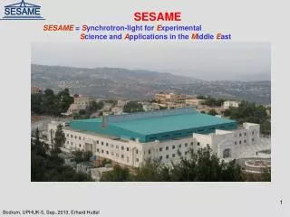
Experimental Program for the Vacuum of CLIC-DR P. Chiggiato The vacuum chambers of the DR are bombarded by synchrotron radiation, electrons-positrons and ions. Such collisions induce gas desorption and photoelectron emission. The most critical vacuum chambers are those in the wiggler magnets because the energetic particle deposition is coupled with the cryogenics constraints. The experimental program should follow three lines: 1- Design, production and static vacuum measurement of the wiggler beam pipe in cryogenic conditions. 2- Definition of the best surface treatment to fulfill the machine requirements (a-C, new NEG, conditioning). The characterization will be given by electron stimulated desorption in our labs. 3- For the chosen geometry of the DR beam pipes, measurements by a synchrotron radiation facility are proposed: desorption yield and photoelectron yield should be measured at a critical energy not far from the expected DR values. A collaboration with ESRF is being prepared. The aim is the installation of a dedicated bench in sector 31, using the large spectrum of the bending magnet. Preliminary test have been already carried out in 2009.
RF prototyping and experiments A. Grudiev • Conceptual design of 1-2GHz systems ready for CDR with 1GHz the baseline • Decision of the final RF frequency should be made in the course of the technical design • RF deflector stability measurements in CTF3, for validating the train recombination • RF design including powering scheme and LLRF for both frequencies • Prototyping based on the final RF design parameters • Design and build 1-2 RF modules and test them in the lab • Experimental program for validation (2013-2016) • High power RF design (high average and peak power level) • LLRF system to provide beam stability (voltage and phase stability tolerances from RTML) • RF system itself in the presence of strong beam loading (both transient and the steady-state) • Experimental set-up • Install RF modules in storage ring with highest possible beam current and energy loss/turn • Standard Bunch frequency 352 MHz or 500 MHz. CERN/collaborator would provide additional high power RF systems as third harmonic system. • Important to be able to fill ring unevenly for studying transient effects. • Necessary beam instrumentation allowing beam size and bunch length measurements down to the level of CLIC DR stability requirements
Summary table All 3 options seems to be feasible but have different issues summarized below φs reduction helps a lot here
Kicker experimental program • Currently kicker built through collaboration Spain-CERN (IFIC Valencia – CIEMAT) and power source in collaboration with SLAC • Experimental program for testing kicker stability with beam (double kicker system), validating low impedance design • Experimental set-up • Need available space to install kicker ( around 3m) without limiting geometrical acceptance • Low horizontal beam size is necessary for validating stability requirements • 50Hz operation may be required for testing kicker reliability • Important to be able to reproduce damping ring train length and gaps for kicker flat top and rise time • High single bunch currents for validating low-impedance design • Necessary beam instrumentation allowing beam size jitter measurements • Extraction transfer line with adjustable well controlled optics for testing double kicker system • Candidate • ATF (especially due to experience with the double kicker system)
Instrumentation experimental program T. Lefevre • Most important, turn by turn, bunch by bunch profile monitor • Necessitates storage ring with ultra-low emittance or very small optics functions (small beam sizes), i.e. in combination with demonstration of ultra-low vertical emittance e.g. SLS (see EU program TIARA-SVET) • Diagnostics based on X-rays, need space not only in the ring (~1m) but also for building a small optical line • Feed-back systems may be part of the package • Need space for feed-back kicker and stripline BPM (most storage rings already have this) • High-intensity beam conditions (typical for B-factories) for triggering instabilities (e.g. SOLEIL is limited by FII at top current of ~500mA) • Storage rings may be good test beds not only for DR diagnostics but for CLIC in general
Low Emittance Rings collaboration • Initiated by the ILC-CLIC working group on damping rings • Workshop organized in January 2010 at CERN identifying items of common interest among the low emittance rings community (synchrotron light sources, linear collider damping rings, b-factories) • Low emittance rings working groups formed • A EU network proposal is under approval (ESGARD) • Interest from 25 institutes worldwide • Next workshop to be organized during 2011