Download
1 / 13
130 likes | 311 Views
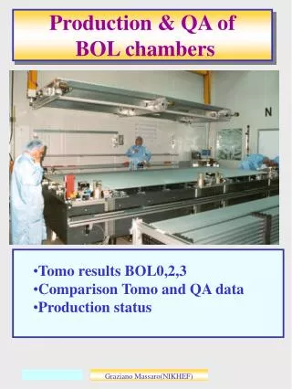
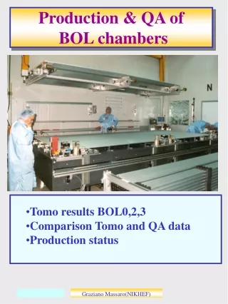
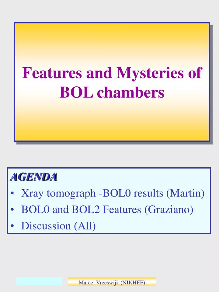
Features and Mysteries of BOL chambers. AGENDA Xray tomograph -BOL0 results (Martin) BOL0 and BOL2 Features (Graziano) Discussion (All). BOL0 - Hypothesis. OBSERVATIONS BOL0 Y -pitch between inner wire-layers: 20um too large Y-Pitch between outer wire-layers: only slightly too large

E N D
Features and Mysteries of BOL chambers AGENDA • Xray tomograph -BOL0 results (Martin) • BOL0 and BOL2 Features (Graziano) • Discussion (All) Marcel Vreeswijk (NIKHEF)
BOL0 - Hypothesis • OBSERVATIONS BOL0 • Y-pitch between inner wire-layers: 20um too large • Y-Pitch between outer wire-layers: only slightly too large • Y-Pitch between multilayers: 75um too small • Hypothesis • Glue shrimp between tubes and spacer? • (2x500um glue gap) • --> measured: <5um effect for 1mm gap • Xplate deforms during gluing. In particular the flange • --> presented today • Additionally: • Re-analysis of BOL0 construction RASNIK readings: ‘cumulative effects’ lead to better agreement! Marcel Vreeswijk (NIKHEF) s
Floppy Xplate wrt tubes =Rotation of unknown relative size @longbeam Longbeam constraints body Xplate locally ‘Tube-length’ bends body Tube direction bends flanges Away from longbeam Marcel Vreeswijk (NIKHEF) s
Sag Adjustment =Rotation of unknown relative size Longbeam constraints body Xplate locally ‘Tube-length’ constraints flanges Tube direction bends flanges Away from longbeam flange bends differently! BOL0 is scanned with sag-adjustment (partially) on! (Longbeam sag is assymetric in BOL0) When we are optimistic: deformation is symmetric for up/down ML. Marcel Vreeswijk (NIKHEF) s
Sag Compensation =Rotation of unknown relative size Longbeam constraints body Xplate locally ‘Tube-length’ constraints flanges Tube direction bends flanges (temporary) Marcel Vreeswijk (NIKHEF) s
XP deformation During BOL2 construction, the flange of the HV xplate was measured with micro-gauges: LBF: Longbeam- Flange BF: Body- Flange For now, BOL2 is still equipped with gauges, located on the inner side of the HV-xplate Marcel Vreeswijk (NIKHEF) s
Start glue Start glue Gluing BOL-0 • Stability Xplates during gluing Layer 1 Yrasnik=2 x Sag Layer 1: dSag=7um Layer 2 Start glue Layer 3 Layer 2: dSag=10um • The sag of the xplates in layer 1 and 2 change in time. • Layer 3,4,5,6: Sag stable Marcel Vreeswijk (NIKHEF) s
Sag Compensation BOL2 Layer 1 Start: -15/2 um • During gluing of • layer 1 and 2, significant changes in xplate sag were observed: • In-stable reduction valves? • Effect of glue viscosity? End: -38/2 um Layer 2 Start: 30/2 um End: 50/2 um 1 deg Marcel Vreeswijk (NIKHEF) s
Conclusions • OBSERVATIONS BOL0 • Y-pitch between inner wire-layers: 20um to large • Y-Pitch between outer wire-layers: only slightly to large: • Effects largely explained by RASNIK measurements during construction. • Flange deformation of order 10um could be ‘baked’ in. • Y-Pitch between multilayers: 75um to small: • Flange deformations of this order are certainly observed. However these deformations appear symmetric and elastic. • Needs more study -> effects of kinematic mounts • direct -in situ- measurement dY of Frascati comb and towers Marcel Vreeswijk (NIKHEF) s
Test @CERN inTomograph (BOL0) Analysis of Martin Woudstra Wire positions RMS 16mm Marcel Vreeswijk (NIKHEF) s
Parallelogram-ness For stability bare spacer Checks distance wrt Comb @ RO side “BOL RO rail Marcel Vreeswijk (NIKHEF) s
Landing-Tool • Problems with lowering gluing tube layers on tube layers due to glue viscosity • Landing tool pre-aligns chamber and ensures flat landing in glue. BOL Tower Effective + Easy Marcel Vreeswijk (NIKHEF) s
Cosmic Ray Stand Marcel Vreeswijk (NIKHEF) s