Download
1 / 16
160 likes | 189 Views
Learn the fundamentals of multiview projections, from basics and principles to techniques such as unfolding a "glass box" for top and right-side views. Understand how to label and visualize surfaces, project depth dimensions, and work with conic sections in both traditional and CAD drawing. Enhance your drafting skills with this in-depth exploration.

E N D
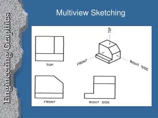
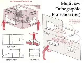
Basics of Projections • Orthographic drawings are the result of projecting the image of a three-dimensional object onto one of six standard planes of projection. The planes of projection intersect each other at fold lines. The six standard planes of projection are often thought of as a "glass box." • Each view in an orthographic projection is aligned with an adjacent view. The principal views most often used are top, front, and right side.
To help project or verify surfaces you can label them with letters, and the corners of surfaces can be labeled with numbers. There are normal, inclined, and oblique surfaces. Normal surfaces appear true size in one principal view and as an edge in the other two principal views. Inclined surfaces appear as an edge view in one of the three principal views. Oblique surfaces do not appear in edge view in any of the principal views.
Basics of Projections - Contd… • Conic sections and irregular curves must be plotted by identifying points on the object. The points can be projected to approximate the boundaries of the curved surface. • Drawing conventions define usual practices for the representation of features such as holes, bosses, ribs, webs, spokes, fillets, and rounds. • Creating CAD drawings involves applying the same concepts as paper drawing. The main difference is that the paper surface is replaced by the monitor screen, and CAD software can draw a line faster and more accurately than most drafters.