Download

1 / 37
380 likes | 401 Views
Learn the differences between axonometric, oblique, and isometric projections. Develop skills in creating isometric and oblique sketches from a multiview drawing using different orientation methods. This chapter provides insights into various types of projections and the steps involved in sketching from actual objects or multiview drawings. Enhance your understanding of isometric axes, sketching guidelines, and techniques for creating accurate pictorial representations.

E N D
Chapter 5 Pictorial Projection
Explainthe difference between axonometric and oblique projection. Explainthe difference between isometric projection and isometric sketch (or draw). Create an isometric and oblique sketches from an actual objectand given multiview drawing. Objectives After completing this chapter, the students will be able to
Topics • Pictorial projections • Axonometric • Oblique Isometric sketch Oblique sketch
Pictorial Projections
B A D A C A B Line of sight Line of sight A B B C D C C D D Pictorial Projection Axonometric Projection Oblique Projection Parallel & normal to picture plane Parallel & oblique to picture plane
B A D C B Line of sight A D C Axonometric Projection
a b c B A a D c C b B a A c b D C Axonometric Projection Type of axonometric drawing Axonometric axis 1. Isometric All angles are equal. Axonometric axis Two angles are equal. 2. Dimetric Axonometric axis None of angles are equal. 3. Trimetric
A A Line of sight B B C C D D Oblique Projection
45o 60o A 30o B C B A D D C Full scale Half scale 45o 45o Oblique Projection Oblique drawing angle Type of Oblique drawing 2) Cabinet 1) Cavalier
Isometric projection vs. Isometric sketch
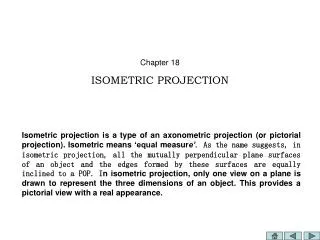
Isometric Projection Rotate 45 about vertical axis Tilt forward (35o16’) All edges foreshorten about 0.8 time.
Forshorten Full scale Isometric sketch Isometric sketch is an isometric view that is drawn in full size. Isometric drawing (Full size) Isometric projection (True projection)
Orientation of Isometric Axes Isometric axes can be arbitrarily oriented to create different views of a single object. Regular isometric Reverse axis isometric Long axis isometric View point is looking down on the top of the object. View point is looking from the right (or left) of the object. View point is looking up on the bottom of the object.
True-length distances show along isometric lines. Isometric line is the line that run parallel to any of the isometric axes. Distance in Isometric Sketch Nonisometric lines Isometric axes
Isometric Sketching
Sketch from an actual object 1. Place the object in the position which its shape and features are clearly seen. 2. Define an isometric axis. 3. Sketching the enclosing box (or cylinder). 4. Estimate the size an and relationship of each details. 5. Darken all visible lines.
Sketch from an actual object STEPS 1. Positioning object. 2. Select isometric axis. 3. Sketch enclosing box. 4. Add details. 5. Darken visible lines.
In isometric sketch/drawing), hidden lines are omittedunless they are absolutely necessary. Note Sketch from an actual object STEPS 1. Positioning object. 2. Select isometric axis. 3. Sketch enclosing box. 4. Add details. 5. Darken visible lines.
Sketch from multiview drawing 1. Interprete the meaning of lines/areas in multiview drawing. 2. Locate the lines or surfaces relative to isometric axis.
Top H Top View Front Side W D Front View Side View H Side D Front Bottom View W Bottom Example 1 : Object has only normal surfaces Regular Reverse
D Nonisometric line q y H y x Front View x W Example 2 : Object has inclined surfaces
x C y E A D F B Front View B D C A E F Example 4 Regular Reverse
In isometric drawing, a circle appears as an ellipse. Isometric ellipse Sketching Steps 1. Locate the center of an ellipse. 2. Construct an isometric square. 3. Sketch arcs that connect the tangent points.
Four-centermethod is usually used when drawn an isometric ellipse with drawing instrument. Isometric ellipse Sketching Steps 1. Locate the center of an ellipse. 2. Construct an isometric square. 3. Construct a perpendicular bisector from each tangent point. 4. Locate the four centers. 5. Draw the arcs with these centers and tangent to isometric square.
Irregular Curve in Isometric Steps 1. Construct points along the curve in multiview drawing. 2. Locate these points in the isometric view. 3. Sketch the connecting lines.
Oblique Sketching
Object Orientation Guidelines Complex features (arc, hole, irregular shape surface) are placed parallel to frontal plane.
Object Orientation Guidelines The longest dimension of an object should be parallel to the frontal plane. GOOD GOOD WORSE WORSE
Object Orientation Guidelines Which one is better ?
D 45 Sketch from actual object ESTIMATE DEPTH ESTIMATE LINES
Sketch from multiview drawing Example 1
Sketch from multiview drawing Example 1
E D C B A Sketch from multiview drawing Example 2
Sketch from multiview drawing Example 2 E D C B A
Sketch from multiview drawing Example 2 E D C B A
Sketch from multiview drawing Example 2 E D C B A