Download
1 / 44
520 likes | 1.02k Views
Numerical study of wave and submerged breakwater interaction. (Data-driven and Physical-based Model for characterization of Hydrology, Hydraulics, Oceanography and Climate Change) IMS-NUS PHUNG Dang Hieu Vietnam Institute of Meteorology, Hydrology and Environment

E N D
Numerical study of wave and submerged breakwater interaction (Data-driven and Physical-based Model for characterization of Hydrology, Hydraulics, Oceanography and Climate Change) IMS-NUS PHUNG Dang Hieu Vietnam Institute of Meteorology, Hydrology and Environment Email: phungdanghieu@vkttv.edu.vn
They are violent too! Fig. 2: Heugh Breakwater, Hartlepool, UK (photo: George Motyka, HR Wallingford) Fig.1: Overtopping of seawall onto main railway - Saltcoats,Scotland (photo: Alan Brampton)
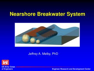
To reduce wave energy Land Breakwater • Submerged • Seawall breaking Seawall supported by porous parts
Structure design diagram Physical Experiments Design Wave Conditions Numerical Simulations Wave Reflection, Transmission Wave Run-up, Rundown, Overtopping Velocity field, Turbulence Wave pressures & Forces upon structures Information For Breakwater & Seawall designs
Some problems of Experiments related to Waves • Physical experiment of Small scale: • Scale effects • Undesired Re-reflected waves • Lager Scale experiment - Costly • Numerical Experiment • Cheap • Avoid scale effects and Re-reflected waves Difficulties: Integrated problems related to the advanced knowledge on Fluid Dynamics, Numerical Methods and Programming Techniques.
What do we want to do? • Develop a Numerical Wave Channel • Navier-Stokes Eq. • Simulation of wave breaking • Simulation of wave and structure interaction • Do Numerical experiments: • Deformation of water surface • Transformation of water waves; wave-porous structure interaction
Concept of numerical wave channel Non-reflective wave maker boundary Open boundary Free surface boundary air Solid boundary water Wave absorber Porous structure
Governing Equations • Continuity Eq. • 2D Modified Navier-Stokes Eqs. (Sakakiyama & Kajima, 1992) extended to porous media (1) (2) (3)
where: (4) CD : the drag coefficient CM: the inertia coefficient gn:: the porosity x ,z: areal porosities in the x and z projections e: kinematic eddy viscosity =n+nt (5)
Turbulence model • Smangorinski’s turbulent eddy viscosity for the contribution of sub-grid scale: (6)
Free-surface modeling • Method of VOF (Volume of fluid) (Hirt & Nichols, 1981) is used: (4) Volume of water F = ; Cell Volume F = 1 means the cell is full of water F = 0 means the cell is air cell 0< F <1 means the cell contains the free surface qF : the source of F due to wave generation source method
Free surface approximation Simple Line Interface Construction- SLIC approximation .1 .6 .5 .6 .4 0 1 1 1 1 .4 0 Hirt&Nichols (1981) .7 1 1 1 1 .2 .9 1 1 1 1 1 Natural free surface 1 1 1 1 1 1 air water .6 .5 .6 .4 .1 0 .4 1 1 1 1 0 present study .7 .2 1 1 1 1 .9 1 1 1 1 1 1 1 1 1 1 1 Piecewise Linear Interface Construction- PLIC approximation
Interface reconstruction P1 P2 O
Numerical flux approximation SLIC-VOF approximation (Hirt&Nichols, 1981) PLIC-VOF approximation (Present study)
Non-reflective wave maker (none reflective wave boundary) Wave generating source Vertical wall Free surface elevation Damping zone Progressive wave area Standing wave area
MODEL TEST • Deformation of water surface due to Gravity • TEST1: Dam-break problem (Martin & Moyce’s Expt., 1952) • TEST2: Unsteady Flow • TEST3: Flow separation • TEST4: Flying water (Koshizuka et al., 1995) • Standing waves • Non-reflective boundary • Wave overtopping of a vertical wall
(Martin & Moyce , 1952) TEST1: Dam-break time=0.085s L time=0s 2L time=0.21s time=0.125s
TEST2 Initial water column
TEST3 Initial water column
TEST4 (Koshizuka et al’s Experiment (1995) Initial water column Solid obstacle
TEST4 time=0.04s obstacle time=0.05s (Koshizuka et al., 1995) Simulated Results
MODEL TEST WITH WAVES • Standing waves • Wave overtopping • Wave breaking
Regular waves in front of a vertical wall Vertical wall
wave overtopping of a vertical wall 11 x 17cm =187cm G2 G1 G12 Wave conditions: Hi= 8.8 & 10.3cm T = 1.6s Wave overtopping 17cm hc=8cm air SWL water h= 42.5cm Experimental conditions
Time profile of water surface at the wave gauge G1 Effects of re-reflected waves
Time profile of water surface at the wave gauge G5 Effects of re-reflected waves
Wave height distribution Vertical wall L: the incident wave length
Overtopping water Effects of re-reflected waves Wave condition: Hi=8.8cm, T=1.6s
Wave breaking Breaking point (x=6.4m from the original point) Run-up Area Surf zone SWL Sloping bottom s=1/35 x=7.275m Experimental conditions by Ting & Kirby (1994) (Hi=12.5cm, T=2s)
Comparison of wave height distribution Breaking point Wave crest curves 2004) Wave trough curves
Velocity comparisons at x=7.275m At z =-4cm At z =-8cm Horizontal velocity Vertical velocity
Interaction of Wave and Porous submerged break water • What is the influence of inertia and drag coefficients on • wave height distributions ? Wave absorber 38 capacitance wave gauges • What is the influence of the porosity of the breakwater on the wave reflection and transmission? G31 G34 G38 H=9.2cm T=1.6s G1 G12 G17 3. What is the effective height of the submerged breakwater? air SWL 29cm Porous break water h=37.6cm water 33cm Objective: to answer the above questions partly by numerical simulations 115cm x x=0
Influence of inertia coefficient on the wave height distribution Breaking point Cd=3.5 1.0<Cm<1.5
Influence of drag coefficient on the wave height distribution Breaking point Cm=1.2 The best combination: Cd=1.5, Cm=1.2
water surface elevations at the off-shore side of the breakwater
Variation of Reflection, Transmission and Dissipation Coefficients versus different Porosities Porosity of Structure
Optimal Depth d Consideration: - top width of the breakwater is fixed, - slope of the breakwater is fixed - change the depth on the top of the breakwater Find: Variation of Reflection, Transmission Coefficients
REMARKS • There are many practical problems related with computational fluid dynamics need to be simulated in which wave-structure interaction, shore erosion, tsunami force and run-up, casting process are few examples. • A Numerical Wave Channel could be very useful for initial experiments of practical problems before any serious consideration in a costly physical experiment later on (water wave-related problem only). • Investigations on effects of wind on wave overtopping processes could be a challenging topic for the present research. THANK YOU