Download
1 / 26
260 likes | 529 Views
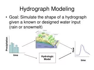
Hydrologic Modeling. The use of physical or mathematical techniques to simulate the hydrologic cycle and its effects on a watershed Most commonly used to simulate stormwater runoff in a watershed. HEC-HMS. US Army Corps of Engineers Hydrologic Modeling SystemUsed to electronically simulate precipitation-runoff processes of dendritic watershed systems Outputs include peak flows and runoff hydrographsOutputs used directly or in conjunction with other programs .

E N D
1. PrePro2004: Comparison with Standard Hydrologic Modeling Procedures
Rebecca Riggs
April 29, 2005
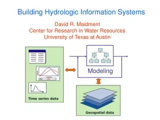
2. Hydrologic Modeling The use of physical or mathematical techniques to simulate the hydrologic cycle and its effects on a watershed
Most commonly used to simulate stormwater runoff in a watershed
3. HEC-HMS US Army Corps of Engineers Hydrologic Modeling System
Used to electronically simulate precipitation-runoff processes of dendritic watershed systems
Outputs include peak flows and runoff hydrographs
Outputs used directly or in conjunction with other programs
4. 3 Components of HMS Basin Model
Watershed Parameters
Meteorologic Model
Precipitation and Evapo-transpiration Parameters
Control Specifications
Start and End Date/Time of Simulation
5. Basin Model Watershed parameters: sub-basins, reachs, junctions, sources, sinks, and reservoirs
Commonly data is derived from contour maps (USGS or survey data), land use maps, and soil maps
Tedious and time consuming
6. Sub-basins
7. Reach Parameters
8. PrePro2004 A GIS pre-processor which extracts hydrologic information from spatial data for HMS modeling
Add-in tool in Arc-GIS interface
Much faster than conventional methods for calculating basin model parameters
9. Study Area College Station, Texas
Castlegate Subdivision
Spring Creek, before confluence with Lick Creek
10. Study Area
11. PrePro2004 Basic Steps Gather data
Fill sinks, create FDIR grid, create FACC grid
Construct stream network
Add inlet, outlet, and/or reservoir
Delineate watershed
Extract HMS elements
Calculate parameters
Calculate curve numbers
Export data to IDM
Export IDM to HMS
Setup HMS project
12. 1. Gather Data DEM, stream vector data, mask grid, soils vector or grid data, land use vector or grid data
DEM source: USGS seamless
Soils and land use (zoning) from COCS
Stream vector data from US EPA Lower Brazos arc data
13. 2. Fill sinks, create FDIR grid, create FACC grid Fill: Cell elevation raised to lowest surrounding cell elevation
FDIR: Flow direction grid
FACC: Flow accumulation grid
14. 3. Construct Stream Network Chose cell threshold = stream drainage area
15. 4. Add Inlet/Outlet/Reservoir
16. 5. Delineate Watershed
17. 6. Extract HMS Elements Under Vectorization tab in Watershed Delineation tool
Creates shapefiles to be directly imported to a target geodatabase
Elements include watershed, reach, junction, source, and reservoirs
Following element extraction can merge basins, but this was not selected in this project
18. 7. Calculate Parameters Generates longest flow path for each sub-basin, HMSCode, and extracts slope and elevation data from DEM
Data stored in �watershed� and �reach� layers
19. 8. Calculate Curve No. Need soils data, land use data, watershed data (previously created), and CN lookup table
20. Curve No. Continued Vector data was used, but raster data could be used if available
Soils data was given by individual HSG, not a % of each
Zoning was used for land use, then equated to the NLCD land use codes manually
After calculating CN and impervious cover are stored in the �watershed� layer
21. 9. Export Data to IDM Prior to this step gage weights can be calculated, a frequency storm is used in this project so gage weighting was skipped
Exports data from previous steps to project and basin geodatabases (preferably empty)
Following this step time of concentration for each subbasin is calculated (Calculate Parameters)
22. 10. IDM to HMS Creates input files for HMS from data stored in basin geodatabase
Basin file
Meteorologic file (if gage data is used)
Must propogate fields with chosen methods for loss rate, transform, and routing
23. 11. Import to HMS Import basin and meteorologic files into HMS
Import background map and grid data
24. Results
25. Basin Comparison
26. Comments The sub-basins would have been more similar had I added more user defined outlets
Time savings is huge
Good for large scale projects, but difficult to accurately define watersheds with tool on small scale (development scale)
27. Questions?