Download
1 / 19
190 likes | 347 Views
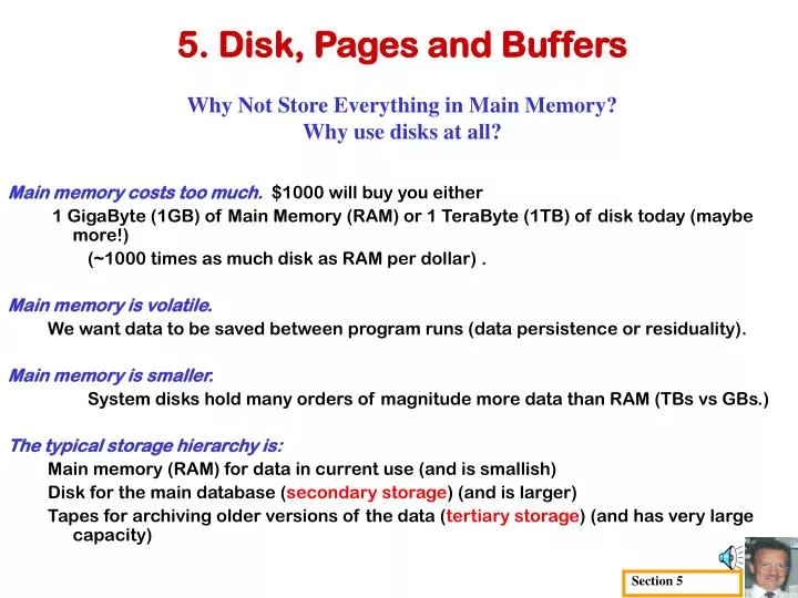
Section 5. 5. Disk, Pages and Buffers Why Not Store Everything in Main Memory? Why use disks at all?. Main memory costs too much. $1000 will buy you either 1 GigaByte (1GB) of Main Memory (RAM) or 1 TeraByte (1TB) of disk today (maybe more!) (~1000 times as much disk as RAM per dollar) .

E N D
Section 5 5. Disk, Pages and BuffersWhy Not Store Everything in Main Memory?Why use disks at all? • Main memory costs too much.$1000 will buy you either • 1 GigaByte (1GB) of Main Memory (RAM) or 1 TeraByte (1TB) of disk today (maybe more!) • (~1000 times as much disk as RAM per dollar) . • Main memory is volatile. • We want data to be saved between program runs (data persistence or residuality). • Main memory is smaller. • System disks hold many orders of magnitude more data than RAM (TBs vs GBs.) • The typical storage hierarchy is: • Main memory (RAM) for data in current use (and is smallish) • Disk for the main database (secondary storage) (and is larger) • Tapes for archiving older versions of the data (tertiary storage) (and has very large capacity)
Section 5 #1 Disks • Secondary storage device of choice. • Main advantage over tapes: random access vs.sequential • Data stored and retrieved in units called disk blocks or pages • Unlike RAM, time to retrieve a disk page varies depending upon location on disk. • Caveat: In NUMA (non-uniform memory access) machines, e.g., NDSU CHPC’s SGI ALTIX, even in RAM, time to retrieve depends upon location (which brick or quad) • Therefore, relative placement of pages on disk has a major impact on DBMS performance!
Arm assembly moves in/out to position a head on a desired track. Spindle Tracks (both sides of platter) Disk head Sector Platters cylinder Arm movement Arm assembly Section 5 #2 Collection of tracks under the heads at any one time is a cylinder. Components of a Disk Only one head reads/writes at any one time (on almost all disks). Block size (the smallest unit of transfer) is a multiple of sector size (which is fixed).
Section 5 #3 Accessing a Disk Page • Delay time to access (read/write) data on a disk block: • seek time (moving arms to position disk head on track) • rotational delay (waiting for block to rotate under head) • transfer time (actually moving of electronic data to/from disk surface) • Seek time and rotational delay dominate. • Seek times can vary from about 1 to 20msec • Rotational delay can vary from 0 to 10msec • Transfer rate can be 1msec per 4KB page • Key to lower I/O cost: reduce seek/rotation delays! Hardware vs. software solutions?
Section 5 #4 Arranging Pages on Disk (clustering) • `Next’ block concept: • blocks on same track, followed by • blocks on same cylinder, followed by • blocks on adjacent cylinder • Blocks in a file should be arranged sequentially on disk (by the above notions of `next’), to minimize seek and rotational delay. • For a sequential scan, pre-fetchingseveral pages at a time is a big win!
Section 5 #5 RAID (redundant array of independent disks) • RAID Disk Array: Arrangement of several disks that gives the abstraction of a single, large disk. • RAID Goals: Increase performance (more concurrent read/write heads) and reliability (redundant data copies are kept) • RAID's two main techniques: • Data striping: Data is partitioned and “striped” across disks; • size of a partition is called the striping unit. • Partitions are distributed over several disks allowing more read/write heads to operate in parallel. • Redundancy: • Redundant info allows reconstruction of data if 1 disk fails.
Disk1 Disk2 Disk3 Disk4 123 4 Disk1 Disk2 Disk3 Disk4 Disk1 Disk2 Disk3 Disk4 4 3 4 3 2 2 1 1 3 4 3 4 1 2 1 2 Section 5 #6 RAID Levels • Level 0: Block striping but no redundancy (e.g., Blocks 1,2,3,4 on Disks 1,2,3,4 resp.) Faster reads (more r/w heads working in parallel) • Level 1: Mirroring (2 identical copies) • Each disk has a mirror image disk (check disk) • Parallel reads, but a write involves 2 disks. • Improved durability • Level 0+1: (sometimes called level 10) • Block Striping • and Mirroring • Faster reads plus improved durability • Level 2: simple bit-striping, Not used these days.
ParityDisk Disk1 Disk2 Disk3 Disk4 1 2 3 4 ParityDisk Disk1 Disk2 Disk3 Disk4 1 2 3 4 Disk0 Disk1 Disk2 Disk3 Disk4 Section 5 #7 RAID Levels 3,4,5 • 1 check disk. Each read/write request involves all disks; disk array can process 1 request at a time (but very rapidly) • Level 3:Bit-Interleaved Parity • Striping Unit = 1 bit bits 1,2,3,4 e.g.,on disks 1,2,3,4, resp. • Level 4: Block-Interleaved Parity • Striping Unit=1 block. blocks 1,2,3,4 • 1 check disk • Parallel reads possible for small requests • large requests can utilize full bandwidth • Writes involve modifying block and check disk • Level 5: Block-Interleaved Distributed Parity • Similar to Level 4, but parity blocks distributed over all disks (striping unit = block) • eliminates Parity Disk hot-spot
Page Requests from Higher Levels BUFFER POOL (page frames) Occupied frame free frame MAIN MEMORY DISK Disk_mgr transfers pages between page-frame > disk choice of frame for a page is dictated by replacement policy DB Section 5 #8 Buffer Management in a DBMS • Data must be in RAM (buffer) for DBMS to operate on it! • LookupTable of <frame#, pageid> pairs is maintained.
Section 5 #9 When a Page is Requested • If requested page (from a higher level) is not in buffer pool: • Choose a frame for replacement • If frame is dirty (has been changed while in RAM), write it to disk first • Then Read the requested page into that frame (and update the LookupTable) • Pin the page (designate it as temporarily non-replaceable) and return its address to requesting higher level layer process. • If requests can be predicted (e.g., in sequential scans), • pages can be pre-fetchedseveral at a time!
Section 5 #10 More on Buffer Management The requestor of a page, when it is done with that page, must unpin it (actually decrement its pin count) and set dirty bit if page has been modified. • Because a page in the buffer pool may be requested concurrently by many higher layer processes, • pin count is used (LookupTable has <frame#, pg-ID, pincnt>) • A page is a candidate for replacement iff pin count = 0. • A note: CC & recovery subsystem may force additional I/O when a frame is chosen for replacement. (e.g., to implement a Write-Ahead Log protocol; more later on that.)
13 14 12 BUFFER POOL 7 write read 9 8 10 11 DISK pages 1 2 3 4 5 6 7 8 9 10 11 12 13 14… Section 5 #11 Buffer Replacement • A frame is chosen for replacement by a replacement policy: • Least-recently-used (LRU) or Most-Recently-Used (MRU) or… • An example is given below, showing that knowledge of access pattern by the buffer manager, can be important – e.g., with LRU: • Extent (multi-block) pre-fetching (and extent writing) would alleviate this situation considerably. 1 2 3 4 5 6 These 6 reads fill the buffer. With LRU, every new read requires a write, flushing a frame (assuming all 6 pages have been change (dirtied))
7 BUFFER POOL 1 2 1 2 3 4 5 6 1 2 3 4 5 6 7 Section 5 #12 Buffer Replacement Policy • The Policy can have a big impact on the number of Inputs and Outputs (I/O’s). It can depend on the access pattern. • Sequential floodingis the bad situation caused by LRU + repeated sequential scans • Can happen when # buffer frames < # pages in sequentially scan. • Each page request causes a flush, whereas, • MRU + repeated sequential scans would not. • A file with 7 blocks is being read sequentially and repeatedly into a buffer pool with 6 page frames. Note, after a while, every page to be read, was just flushed. Pgs 1-6 read in order. To read page-7, LRU flushes page 1 Second scan begins, requiring page-1, but it was just flushed! 2nd scan now needs page-2, but it was just flushed! Etc.
Section 5 #13 DBMS vs. OS File System OS can do disk space and buffer management. Why not let OS manage these tasks? • Differences in OS support: portability issues • Some OS limitations, e.g., files can’t span disks. • Buffer management in DBMS requires ability to: • pin a page in buffer pool, force a page to disk (important for implementing CC & recovery), • adjust replacement policy, and pre-fetch pages based on access patterns in typical DB operations.
Base address (B) Address = B+L1+L2 Section 5 #14 Record Formats: Fixed Length fields F1 F2 F3 F4 L1 L2 L3 L4 Field lengths • Info about field types same for all records in a file • can access via offsets stored in systemcatalogs
F1 F2 F3 F4 4 $ $ $ $ Fields Delimited by Special Symbols Field Count F1 F2 F3 F4 Array of Field Offsets Section 5 #15 Record Formats: Variable Length • Two alternative formats (assuming a fixed number of fields): • The 2nd alternative offers direct access to ith field, efficient storage • of nulls(special don’t know value); low directory overhead.
RecSlot 1 Slot 1 RecSlot 2 Slot 2 Free Space . . . . . . RecSlot N Slot N Slot M N . . . 1 1 1 M 0 M ... 3 2 1 number of records number of records PACKED pg format UNPACKED, BITMAP Section 5 #16 Page Formats: Fixed Length Records • Record ID (RID) = <page id, slot #>. • In PACKED, moving records for free space mgmt changes RID. That may not be acceptable (RIDs are to be permanent IDs).
Rid = (i,N) Rid = (i,2) Rid = (i,1) * Pointer to start of free space * N * N . . . 2 1 # of record slots SLOT DIRECTORY Section 5 #17 UNPACKED, RECORD POINTER Page Format (for Variable Length Records) Page i • Can move records on page without changing RID; so, attractive for fixed-length records too. …
Section 5 Thank you.