Download

1 / 113
1.24k likes | 2.02k Views
Training Exercises VERICUT for Pro/ENGINEER. Machine Simulation. Introduction. Terms ‘MS’ stands for ‘Machine Simulation’ in this exercise. Exercise 1 - Outline. Outline 3 axis milling machine Work in Pro/E Create machine components and assembly in Pro/E

E N D
TrainingExercises VERICUT for Pro/ENGINEER Machine Simulation
Introduction • Terms • ‘MS’ stands for ‘Machine Simulation’ in this exercise
Exercise 1 - Outline • Outline • 3 axis milling machine • Work in Pro/E • Create machine components and assembly in Pro/E • Export STL file of each machine component against Machine Zero CSYS • Create tool path file(NCL and TAP) using Pro/NC and G-Post • Work in VERICUT Machine Simulation • Build machine kinematics in VERICUT Machine Simulation • Load machine components (STL file) to VERICUT MS • Load Control file • Save MCH, CTL and JOB file in your working directory • Test machine with MDI • Job, Machine setting • Create or load tool library file, tool gauge length setting • Load tool path file and simulate tool path
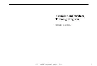
z-axis base-z-slide z-axis-cylinder stock fixture y-axis base x-axis base-x-slide Exercise 1 - 3 axis milling machine • Build 3 axis milling machine and simulate tool path • Work in Pro/E • Preparation • Copy all the machine simulation exercise folder and files to your computer, set Pro/E working directory to: …\exercise 1 • Machine components and assembly • In Pro/E, Open file ‘3axis-mill.asm’
Exercise 1 - 3 axis milling machine • Export component: ‘base.prt’ in STL format • In Pro/E, choose: File/Export/Model/STL • Select ‘Include’, pick part ‘BASE.PRT’, click ‘Done Sel’ • Click Pick Coordinate System icon, select machine zero ‘ACSO’ • Give chord Height=0.1, File name: ‘base’ • Click ‘Apply’
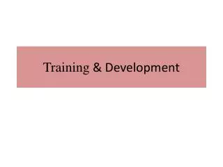
base-y-slide z-axis y-axis z-axis-cylinder fixture x-axis stock base base-z-slide Exercise 1 - 3 axis milling machine • Export all of other components in STL format • Tips • Choose the right Coordinate System - machine zero (ACSO) for all components, because there is no rotary axis on this machine • Give Chord Height: 0.1 or smaller • Change file name • Pro/E assembly ‘3ax-mill.asm’ includes two ‘base-y-slide’ components, choose both of them when exporting ‘base-y-slide’, same comments for ‘base-z-slide’
Exercise 1 - 3 axis milling machine • Work in VERICUT Machine Simulation • Access VERICUT Machine Simulation • In command line, type in ‘proems’ then click enter • Or click batch file ‘proems.bat’ (‘$PRO_DIRECTORY \bin\proems.bat’) • Choose: File/New • Save JOB file in your working directory (… \exercise 1) • In MS, choose: File / Save as, give file name ‘3ax-mill.job’ • Build machine kinematics • In MS, choose: Machine / Components
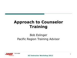
Components Tree Exercise 1 - 3 axis milling machine • Build components tree as following figure shows • In components window, click Add • Add base component: In Add components window, give type as base, color as cyan, then click ‘Apply’
Tool Z Linear Y Linear Exercise 1 - 3 axis milling machine • Using the same method to add other components, make sure ‘Type’, ‘Color’, motion axis, and ‘Connect To’ is right. See following figure for details.
X Linear Fixture Stock Exercise 1 - 3 axis milling machine • Components: X-Linear, Fixture and Stock • After finish last component - ‘Stock’, click OK in Add Component window
Exercise 1 - 3 axis milling machine • Load STL files to VERICUT MS • Load base STL files • In Components window, choose ‘Base’ (Base is highlighted), click STL file icon • Open file ‘base.stl’, (find this file in …\exercise 1 folder) • Using the same method, load STL files: ‘base-y-slide.stl’, ‘base-z-slide.stl’, to component base.
Exercise 1 - 3 axis milling machine • Load STL files to other components • Load ‘z-axis.stl’ and ‘z-axis-cylinder.stl’ to component Z • Load ‘y-axis.stl’ to component Y • Load ‘x-axis.stl’ to component X • Load ‘fixture.stl’ to component Fixture • Load ‘stock.stl’ to component Stock • Change color of Primitives • In Components window, choose ‘base-y-slide.stl’, click ‘Atrib button’, choose Color: White • Using save method, change color of ‘base-z-slide.stl’ to white • Change ‘z-axis-cylinder.stl’ to color white
Gauge Point 15.2 Machine Zero Exercise 1 - 3 axis milling machine • Change Tool connect position • In Pro/E, find distance from gauge point to work table plane (machine zero), It is 15.2 inch. We will move tool connect position from machine zero to gauge point • In VERICUT MS, choose: Machine / Components • In Components window, choose: ‘Tool’, then click Modify • In Modify window, set Connect position=(0 0 15.2), then click OK • Close Components window
Exercise 1 - 3 axis milling machine • Save machine file in your working directory • In VERICUT MS, choose: Machine / Save as, give file name ‘3ax-mill.mch’, make sure you save it in …\exercise 1 folder • Load control file • In VERICUT MS, choose: Control / Open, open file ‘generic.ctl’, find this control file in category ‘CGTECH_RP2LIB’ • Save control file in your working directory • In VERICUT MS, choose: Control / Save as, give file name ‘generic.ctl’, make sure save it in …\exercise 1 folder
Exercise 1 - 3 axis milling machine • Test your machine with MDI • In VERICUT MS, choose: Job / MDI • Test X axis, type in ‘x10’ in MDI, click Apply. Notice movement of X axis • Test negative direction of X axis (x-10) • Test Y and Z axis • (Notes: if axis doesn’t move, check if you load control file correctly)
7.7 Exercise 1 - 3 axis milling machine • Set machine table • In Pro/E, use Analysis/Measure, check distance between gauge point to stock surface, It is 7.7 inch. We will set top surface center of stock as programming zero • In VERICUT MS, choose: Machine / Table • In Machine Table window, choose: Table Name=‘Input Program Zero’, Sub-System ID=1, Index=1, Values=‘0 0 -7.7’. Click Add, then close • (Notes, Machine Table contents can also be defined in Job Table, if a Job Table is defined, it will over write Machine Table)
Exercise 1 - 3 axis milling machine • Set Travel Limits • In VERICUT MS, choose: Machine / Travel Limits • In Travel Limits window, type in Min and Max travel limits of each axis, then click Modify • See following figure for limits value of 3 axis • Toggle Overtravel Detection On • Click OK
Exercise 1 - 3 axis milling machine • Collision setup • In VERICUT MS, choose: Job / Collision • Set: Component 1=Fixture, Component 2=Tool, Tolerance=0.1 • Toggle Collision Detection On • Click OK
Exercise 1 - 3 axis milling machine • Tool library • Method 1, retrieve tool library in VERICUT exercise 4a&b folder • copy file ‘cgtpro.tls’ from ‘VERICUT exercise 4a&b folder’, paste it in your current working directory - ‘VERICUT MS exercise 1 folder’ • In VERICUT MS, choose: Tools / Tool File, open file ‘cgtpro.tls’, find it in your current working directory • Change tool gauge length. In VERICUT MS, choose: Tools / Tool Manager • In Tool Manager window, click Modify
Exercise 1 - 3 axis milling machine • In Tool Modify window, click Properties • In Tool Properties window, set Gage Length=4, click OK • In Tool Modify window, click OK • In Tool Manager window, click Save, then Close
Exercise 1 - 3 axis milling machine • Method 2, create tool library in VERICUT MS by yourself • In Tool Manager window, click Add • In Tool Add window, give: ID=1, Description=‘1 inch FEM’, • Choose FEM icon, give: Diameter=1, Length=4, click Add then click OK • Save tool library file. In Tool Manager window, choose: File / Save as, give file name ‘3ax-mill.tls’, save it in exercise 1 folder • Close Tool Manager window • Click ‘Yes’ in the small question window
Exercise 1 - 3 axis milling machine • Load tool path • In VERICUT MS, choose Job / Setting • In Job Settings window, open Toolpath file ‘tool-com.tap’, find this file in exercise 1 folder • Other settings: see following figure for details • For Log file, give file name: ‘3ax-mill.log’, and select exercise 1 folder • In Job Setting window, click OK • Reset Machine Simulation • Run machine simulation
Exercise 2 - Outline • Outline • 4 axis milling machine • Build machine kinematics • Load STL files • Machine Table, Travel Limits, Collision setting • Load tool library, set tool gauge length offset • Load tool path file, control file • Tool path simulation
Exercise 2 - 4 axis milling machine • Build 4 axis milling machine • Build machine kinematics • See following figures for machine kinematics • Make sure component Type, Connect to, Motion axis and Connect Position is right • Notice connect position of rotary axis A is: (0 0 4), Design is: (0.5 0 0) • (Notes: For Multi-Axis machine uses CSYS on rotary centerline for rotary axis)
Exercise 2 - 4 axis milling machine • Build machine kinematics
Exercise 2 - 4 axis milling machine • Build machine kinematics
Exercise 2 - 4 axis milling machine • Build machine kinematics
Exercise 2 - 4 axis milling machine • Load STL files • Base - ‘base.stl’ • Z - ‘head.stl’ and ‘spindle.stl’ • Tool - Nothing • Y - Nothing • X - ‘table.stl’ • Other - ‘rotary_box.stl’ • A - ‘rotary_chuck.stl’ • Design - ‘ncmach.stl’ • (Notes 1: all Primitives connect position is: [0 0 0] ) • (Notes 2: find STL files in …\exercise 2 folder)
Exercise 2 - 4 axis milling machine • Set Machine Table • See following Machine Table figure for details • Set Travel limits • See following Travel Limits figure for details • Save machine file • Give file name: ‘prolight.mch’, save it in …\exercise 2 folder
Exercise 2 - 4 axis milling machine • Job setting • Load tool path file: ‘op010.tap’, find this file in …\exercise 2 folder • Other settings, see following figure • Collision setup • See following Collision Setup figure for details
Gauge Point Exercise 2 - 4 axis milling machine • Load tool library and set tool gauge length offset • Load tool library file ‘ncmach_gage.tls’, find it in …\exercise 2 folder • Set gauge point at top of each tool • Control file • Load control file ‘tmc2000.ctl’, find this file in …\exercise 2 folder • Save Job file • Give JOB file name: ‘prolight.job’, save it in …\exercise 2 folder • Tool path simulation
Exercise 2a- Outline • Outline • 5 axis laser machine • In Pro/E, export components in STL format • Base and linear axis - Against Machine Zero CSYS • Rotary axis - Against CSYS at rotary center • Build machine kinematics, rotary axis and tool connect position calculation • Load STL files to machine • Machine Table, initial machine location, RTCP pivot offset calculation • Load tool library and set gauge length offset • Load tool path file, control file • Tool path simulation
XAXIS ZAXIS YAXIS CAXIS DAXIS Base Table Exercise 2a - 5 axis laser machine • Build 5 axis laser machine • Preparation • Set Pro/E working directory to …\exercise 2a • Open file ‘laserdyne.asm’ • Export components in STL format • Export base and all linear axis using CSYS at machine zero
CAXIS DAXIS Exercise 2a - 5 axis laser machine • Export rotary components (C and D axis) using CSYS at centerline of rotary axis • Using ‘ACS0’ for CAXIS, and ‘ACS1’ for DAXIS • (Notes: Use same name as Pro/E part for STL files)
Exercise 2a - 5 axis laser machine • Build machine kinematics & load STL files • Base • Type: Base, Name: Base, Color: Blue , Mixed Mode: Shade, Angles: (0 0 0) • Primitives: ‘base.stl’, Color, Inherit, Position (0 0 0), Angle (0 0 0) • XAXIS • Type: X Linear, Name: X, Motion Axis, X, Connect To: Base, Connect Position: (0 0 0) Color: Cyan , Mixed Mode: Shade, Angles: (0 0 0) • Primitives: ‘xaxis.stl’, Color, Inherit, Position (0 0 0), Angle (0 0 0) • ZAXIS • Type: Z Linear, Name: Z, Motion Axis, Z , Connect To: X, Connect Position: (0 0 0) Color: Magenta , Mixed Mode: Shade, Angles: (0 0 0) • Primitives: ‘zaxis.stl’, Color, Inherit, Position (0 0 0), Angle (0 0 0) • YAXIS • Type: Y Linear, Name: Y, Motion Axis: Y, Connect To: Z, Connect Position: (0 0 0) Color: Yellow , Mixed Mode:Shade, Angles: (0 0 0) • Primitives: ‘yaxis.stl’, Color, Inherit, Position (0 0 0), Angle (0 0 0)
Exercise 2a - 5 axis laser machine • CAXIS • Type: C Rotary, Name: C, Motion Axis: Z, Connect To: Y, Connect Position: (0, -16.5, 21) Color: orange , Mixed Mode: Shade, Angles: (0 0 0) • Primitives: ‘caxis.stl’, Color, Inherit, Position (0 0 0), Angle (0 0 0) • DAXIS • Type: B Rotary, Name: D, Motion Axis: Y, Connect To: C, Connect Position: (0 8 -6) Color: Tan , Mixed Mode:Shade, Angles: (0 0 0) • Primitives: ‘daxis.stl’, Color, Inherit, Position (0 0 0), Angle (0 0 0) • Tool • Type: Tool, Name: Tool, Motion Axis: Z, Connect To: D, Connect Position: (0, 8.5, -15) Color: Red , Mixed Mode: Shade, Angles: (0 0 0) • Table • Type: Other, Name: Table, Connect To: Base, Connect Position: (0 0 0) Color: Blue , Mixed Mode: Shade, Angles: (0 0 0) • Primitives: ‘table.stl’, Color, Inherit, Position (0 0 0), Angle (0 0 0)
Components Tree Exercise 2a - 5 axis laser machine • Design • Type: Design, Name: Design, Connect To: Table, Connect Position: (0 0 0) Color: Green , Mixed Mode: Shade, Angles: (0 0 0) • Primitives: ‘test_laserdyne.stl’, Color, Inherit, Position (0 0 0), Angle (0 0 0)
C-axis CSYS D-axis CSYS -6 21 8 Machine Zero -16.5 Exercise 2a - 5 axis laser machine • Rotary axis & tool connect position calculation • C-axis connect position is measured from Machine Zero to C-axis CSYS • D-axis connect position is measured from C-axis CSYS to D-axis CSYS • Tool connect position is measured from D-axis CSYS to Gauge Point (in this case it is Machine Zero)
15 -16.5 Exercise 2a - 5 axis laser machine • Set machine table • Set Initial Machine Location=(0 0 20) • Set RTCP pivot offset=(0 -16.5 15) • RTCP Offset Xval-Zval are calculated by subtracting the location of the Tool component origin from the rotary pivot point location (with all axes at their Initial Machine Location ) • Save machine file
Exercise 2a - 5 axis laser machine • Load tool library and set gauge length offset • Load file ‘tool.tls’, find it in exercise 2a folder • Set gauge offset=8 • Load control • Load control file ‘laserdyne.ctl’, find it in exercise 2a folder • Load Toolpath file • Load file ‘op010.tap’, find it in exercise 2a folder • Save JOB file • Run simulation
Exercise 3 - Outline • Outline • Build your own machine • Choose one machine from list shown in next 7 slides • Build machine components and assembly in Pro-E • Export components in STL format against right CSYS • Create machine kinematics in VERICUT Machine Simulation • Load machine components (STL file) to VERICUT MS • Load control file (fan16M, find it in category of CGTECH_RP2LIB) and save it in your current directory • Machine & Job setting • Test your machine with MDI • Create or load tool library file, set tool gauge length • Create Post-Processor (optional), generate TAP file • Load a tool path file (TAP file), run simulation
3 Axis Vertical Mill 3 Axis Horizontal Mill Exercise 3 - Build your own machine
4 Axis Vertical Mill Table A 4 Axis Horizontal Mill Table B Exercise 3 - Build your own machine
5 Axis Vertical MillHead A on B 5 Axis Vertical MillHead B / Table A Exercise 3 - Build your own machine
5 Axis Vertical Milltables A on C 5 Axis Horizontal MillHeads A on B Exercise 3 - Build your own machine
5 Axis Horizontal Milltables B on A 5 Axis Horizontal MillHead A / Table B Exercise 3 - Build your own machine
Exercise 3 - Build your own machine • 5 Axis Gantry Mill - Heads B on C
Exercise 3 - Build your own machine • 5 Axis Gantry Mill - Heads A on B
Exercise 4, 4a, 4b • Exercise 4 • Menu View • Attributes • View Select/Store • Exercise 4a • Menu Job • Job Setting • Job Table • Collision • Exercise 4b • Menu Machine • Machine Tables • Travel Limits
Exercise 4 - Menu/View • Menu View • Open file ‘prolight.job’ in …\exercise 4 folder • Attributes • In VERICUT MS, choose: View / Attributes • Show CSYS • Toggle Component Origin, Primitive Origin and Machine Zero On, then click Apply • CSYS appears