Download
1 / 24
250 likes | 373 Views
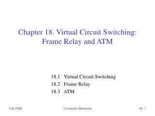
Ch 18. Virtual Circuit Networks. Old WAN Technology. X.25 Virtual-circuit switching network (designed in 1970s) Operating at the network layer and below additional encapsulation of IP packets Low data rate: 64 Kbps Large overhead: flow & error controls at multiple layers

E N D
Old WAN Technology • X.25 • Virtual-circuit switching network (designed in 1970s) • Operating at the network layer and below additional encapsulation of IP packets • Low data rate: 64 Kbps • Large overhead: flow & error controls at multiple layers • Leasing T-1 or T-3 lines • Costly, since it requires n(n-1)/2 lines to connect n branches (mesh networks) • Inefficient and cannot handle “bursty data”
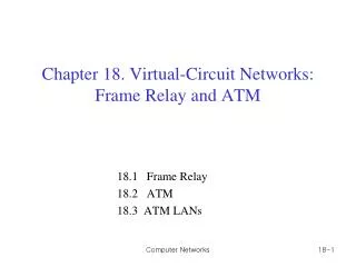
18.1 Frame Relay • Virtual-circuit WAN • Higher speed: 1.544 Mbps or 44.376 Mbps • No network layer: operates in PHY and data link layers • Allows bursty data • Support large frame up to 9000 bytes • Error detection only (no flow control or error control)
Architecture • Virtual circuits • A VC is identified by data link connection id (DLCI) • Support both permanent and switched virtual circuits • Switch has a table with (incoming-port, DLCI) pairs as we have discussed in Chapter 8 • Data link layer • Addressing (DLCI) • Congestion control • Error detection • Physical layer • No specific protocol is defined
Frame Format • DLCI: address • Command/response (C/R): not used • Extended address (EA) • Forward(destination) explicit congestion notification (FECN) • Backward(sender) explicit congestion notification (BECN) • Discard eligibility (DE): priority level of frame when a frame needs to be discarded
Extended Address • To increase the range of DLCI, the Frame Relay address have been extended from the original 2-byte address to 3- or 4-byte addresses. • Three address formats by setting EA
Other Options • To handle frames arriving from other prototocls .Frame relay uses assembler/disassembler (FRAD) • Mux/demux frames from other protocols • Voice over frame relay (VOFR), voice is digitized (PCM) and the compressed • Quality is not good as a circuit-switched network • Originally Frame relay was designed to provide PVC connections. Local management information (LMI) is added to provide more management features • Keep-alive (check if data is flowing), multicast, switch status check
18.2 ATM • Goals of Asynchronous Transfer Mode (ATM) • High data rate (e.g., transmission over optical fiber) • Interface with existing systems providing WAN inter-connectivity • Low-cost implementation • Inter-operability with legacy telephone systems • Connection-oriented for accurate and predictable delivery • Move most functions to hardware
Cell Networks • Problem of existing systems • Multiplexing frames of different size can lead to “unfair delay” for small frames • Cell (a small fixed-size data block) network that uses the cell as the basic unit of data exchange can solve the problem
ATM Architecture • Uses asynchronous time-division multiplexing • User-to-network interface (UNI) and network-to-network interface (NNI)
Virtual Connection • Virtual circuit (VC) • A single message flow • Virtual path (VP) • A set of VCs between two switches • Transmission path (TP) • Physical connection between two end points
ATM Cell • A virtual circuit is uniquely identified by a pair of (VPI, VCI) • Cell (the basic data unit) includes (VPI, VCI) • Switching/routing
Layering Structure • PHY can be any physical layer • Originally intended for SONET • ATM layer • Routing, traffic management, switching, multiplexing • Application adaptation layer (AAL) • Data segmentation to fit in a cell
ATM Header • Header format • Generic flow control (GFC): UNI level • VPI and VCI • Payload type (PT) • Cell loss priority (CLP): congestion control • Header error correction (HEC): CRC to correct errors
AAL Layer – AAL1 • Support any type of payload • Four versions: AAL1, AAL2, AAL3/4, AAL5 • AAL1 • Support applications with constant bit rates - Sequence number (SN): 4-bit - Sequence number protection (SNP): 4-bit
AAL Layer – AAL2 • AAL2 • Intended to support variable-data-rate bit stream • Used for low-bit-rate traffic and short-frame traffic
AAL Layer – AAL3/4 • AAL3/4 • For connection-oriented and connectionless services
AAL Layer – AAL5 • AAL5 • Simple and efficient adaptation layer (SEAL)
ATM Layers in Devices and Switches • ATM has a congestion control and quality of service
18.3 ATM LANs • Adopt ATM technology to LANs • High data rate • Support permanent and temporary connections • Support multimedia traffic with different bandwidths • Pure ATM and Legacy ATM LANs
ATM LANs • Mixed architecture • Issues in LAN Emulation (LANE) • Connectionless versus connection-oriented • Physical addresses versus virtual-circuit identifiers • Multicasting and broadcasting • Interoperability
LAN Emulation (LANE) • Client/Server model • LAN emulation client (LEC): Let upper layers unaware of the existence of the ATM technology • LAN emulation configuration server (LECS): initial connection between the client and LANE • LAN emulation server (LES): create virtual circuit for a request of frame delivery • Broadcast/unknown server (BUS): responsible for multicast and broadcast service
Homework • Exercise • 17 • 20 • 21 • 28