Download
1 / 28
300 likes | 482 Views
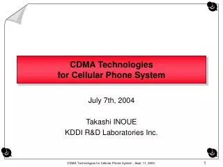
Week 16 Lecture 1. CDMA Technologies for Cellular Phone System. 3rd. Generation (2000s). 2nd. Generation (1990s). Digital. 1st.Generation (1980s). GSM DECT DCS1800 CT2 PDC PHS IS-54 IS-95 IS-136 UP-PCS. Analog. NMT CT0 TACS CT1 AMPS. Evolution of Cellular Systems.

E N D
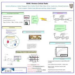
Week 16 Lecture 1 CDMA Technologies for Cellular Phone System
3rd. Generation (2000s) 2nd. Generation (1990s) Digital 1st.Generation (1980s) GSM DECT DCS1800 CT2 PDC PHS IS-54 IS-95 IS-136 UP-PCS Analog NMT CT0 TACS CT1 AMPS Evolution of Cellular Systems IMT-2000 CDMA2000 W-CDMA
Requirements for 3G mobile systems • High Capacity • Tolerance for interference • Privacy • Tolerance for fading • Ability to various data rate transmission • Flexible QoS CDMA meets all of them!
Multiple Access Methods Base Station Forward link Reverse link Mobile Station Mobile Station Mobile Station Mobile Station
Frequency Division Duplex (FDD) • Forward link frequency and reverse link frequency is different • In each link, signals are continuously transmitted in parallel. Forward link (F1) Reverse link (F2) Base Station Mobile Station
Example of TDD Systems Mobile Station Base Station Transmitter Transmitter BPF BPF F1 F1 Receiver Receiver Synchronous Switches BPF: Band Pass Filter
Radio Spectrum Base-band Spectrum B Code A B Frequency Code A Code B A C C B C B B A B A A C A A B Time What is CDMA ? Use codes to spread spectrum Sender Receiver
Power Density TIME spreading sequence (spreading code) Base-band Frequency Power Density 10110100 Radio Frequency How to spread spectrum... Direct Sequence (DS) user data data rate Modulation (primary modulation) Spreading (secondary modulation) Tx
Power Density TIME spreading sequence (spreading code) Radio Frequency you can find the spreading timing which gives the maximum detected power, and 10110100 10110100 10110100 10110100 10110100 01001011 gathering energy ! Accumulate for one bit duration 00000000 00000000 11111111 Demodulated data 0 0 1 Base-band Frequency Demodulating DS Signals (1/2) If you know the correct spreading sequence (code) , received signal
Power Density TIME spreading sequence (spreading code) Radio Frequency you cannot find the spreading timing without correct spreading code, and 10101010 10101010 10101010 10110100 10110100 10110100 10110100 01001011 10110100 Accumulate for one bit duration No data can be detected - - - Demodulated data Base-band Frequency Demodulating DS Signals (2/2) If you don’t know the correct spreading sequence (code) ••• received signal
Power Density Power Density Power Density Noise Radio Frequency Radio Frequency Base-band Frequency With correct code (and carrier frequency), data can be detected. With incorrect code (or carrier frequency), SS-signal itself cannot be detected. Power Density Base-band Frequency Feature of SS Privacy, Security Power density of SS-signals could be lower than the noise density. •••••• •••••• de-modulator transmitted SS-signal received signal Noise They cannot perceive the existence of communication, because of signal behind the noise.
Freq. Freq. Freq. Freq. DS-CDMA System Overview (Forward link) CDMA is a multiple spread spectrum. Freq. Freq. BPF Data A BPF Despreader Data A MS-A Code A Code A Freq. Freq. BPF Data B BPF Despreader Data B MS-B Code B Code B ••• BS ••• Difference between each communication path is only the spreading code
DS-CDMA (two types) • Synchronous DS-CDMA : • Perfect Orthogonal Codes are used. (Walsh code etc.) • Asynchronous DS-CDMA : • Pseudo-random Noise (PN) codes • e.g. Gold codes
Reverse Link (Up Link) Asynchronous Chip Timing A B Big Interference from A station B A Signal for B Station (after re-spreading) Signals from A and B are interfering each other. 1. Asynchronous DS-CDMA
A B A A Less Interference for A station Forward Link (Down Link) Signal for B Station (after re-spreading) Synchronous Chip Timing 2. Synchronous DS-CDMA Synchronous CDMA Systems realized in Point to Multi-point System. e.g., Forward Link (Base Station to Mobile Station) in Mobile Phone.
path-1 Power path-2 path-3 path-2 Path Delay path-1 path-3 Power Time Mobile Propagation Environment ・・・ Multi-path Fading multi-path propagation Mobile Station (MS) Base Station (BS) The peaks and bottoms of received power appear, in proportion to Doppler frequency.
path-1 Power path-2 path-3 Path Delay Power Detected Power Time Fading in non-CDMA System With low time-resolution, different signal paths cannot be discriminated. ••• These signals sometimes strengthen, and sometimes cancel out each other, depending on their phase relation. ••• This is “fading”. ••• In this case, signal quality is damaged when signals cancel out each other. In other words, signal quality is dominated by the probability for detected power to be weaker than minimum required level. This probability exists with less than two paths. In non-CDMA system, “fading” damages signal quality.
path-1 Power path-2 path-3 Path Delay path-1 Power path-3 CODE A with timing of path-1 Path Delay path-2 Power path-1 Power path-2 CODE A with timing of path-2 Path Delay Fading in CDMA System ... Because CDMA has high time-resolution, different path delay of CDMA signals can be discriminated. ••• Therefore, energy from all paths can be summed by adjusting their phases and path delays. ••• This is a principle of RAKE receiver. interference from path-2 and path-3 CDMA Receiver Synchronization Adder CDMA Receiver ••• •••
path-3 path-2 Power path-1 Fading in CDMA System (continued) In CDMA system, multi-path propagation improves the signal quality by use of RAKE receiver. Detected Power Power RAKE receiver Time Less fluctuation of detected power, because of adding all energy .
Near-Far Problem P PL-a CDMA Transmitter DATA A CDMA Receiver Demodulated DATA CODE A P PL-b CODE A CDMA Transmitter DATA B When user B is close to the receiver and user A is far from the receiver, Path loss a (PL-a) could be much bigger than PL-b. In this case, desired signal power is smaller than the interfered power. CODE B
A B Power Control... When all mobile stations transmit the signals at the same power (MS), the received levels at the base station are different from each other, which depend on the distances between BS and MSs. Moreover, the received level fluctuates quickly due to fading. In order to maintain the received level at BS, power control technique must be employed in CDMA systems. from A from B Detected Power Time
((( measuring received power decide transmission power power control command estimating path loss measuring received power calculating transmission power Transmit next Power Control (continued) Open Loop Power Control Closed Loop Power Control Only MH does something; BS doesn’t do anything! ① ② ② transmit about 1000 times per second transmit ①
f3 f2 f4 f1 f7 f5 f6 cell : a “cell” means covered area by one base station. Frequency Allocation (1/2) In FDMA or TDMA, radio resource is allocated not to interfere among neighbor cells. • Neighbor cells cannot use the same (identical) frequency band (or time slot). • The left figure shows the simple cell allocation with seven bands of frequency. • In actual situation, because of complicated radio propagation and irregular cell allocation, it is not easy to allocate frequency (or time slot) appropriately.
Frequency Allocation (2/2) In CDMA, identical radio resource can be used among all cells, because CDMA channels use same frequency simultaneously. • Frequency allocation in CDMA is not necessary. • In this sense, CDMA cellular system is easy to be designed.
switching Cell A Cell B Soft Handoff (1/2) • Handoff : • Cellular system tracks mobile stations in order to maintain their communication links. • When mobile station goes to neighbor cell, communication link switches from current cell to the neighbor cell. • Hard Handoff : • In FDMA or TDMA cellular system, new communication establishes after breaking current communication at the moment doing handoff. Communication between MS and BS breaks at the moment switching frequency or time slot. Hard handoff : connect (new cell B) after break (old cell A)
Soft Handoff (2/2) • Soft Handoff : • In CDMA cellular system, communication does not break even at the moment doing handoff, because switching frequency or time slot is not required. transmitting same signal from both BS A and BS B simultaneously to the MS Σ Cell B Cell A Soft handoff : break (old cell A) after connect (new cell B)
Conclusion • CDMA is based on the spread spectrum technique which has been used at military field. • CDMA cellular system is deemed superior to the FDMA and TDMA cellular systems for the time being. • Therefore, CDMA technique becomes more important in radio communication systems.