Download
1 / 13
130 likes | 314 Views
NCSX PF Coils. Michael Kalish. NCSX Coil Planar Coils. Upper PF Coils. TF Coils. Lower PF Coils. PF Coils Design. PF4. PF5. PF1. PF6. PF Coil Cross Section. PF Coils of conventional design Rectangular cross section Round Geometry. PF Coil Drawings.

E N D
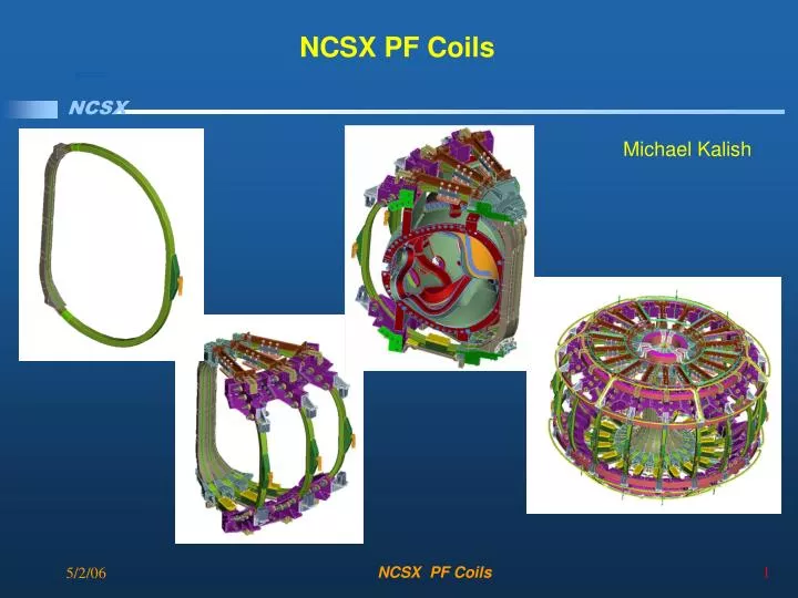
NCSX PF Coils Michael Kalish NCSX PF Coils
NCSX Coil Planar Coils Upper PF Coils TF Coils Lower PF Coils NCSX PF Coils
PF Coils Design PF4 PF5 PF1 PF6 NCSX PF Coils
PF Coil Cross Section • PF Coils of conventional design • Rectangular cross section • Round Geometry NCSX PF Coils
PF Coil Drawings PF Coil drawings are not final but adequate for estimating cost and schedule. NCSX PF Coils
PF Coils, Conductor A single copper conductor size is used for all four different types of PF coils to simplify their manufacture and reduce costs. NCSX PF Coils
Center Stack Assembly, PF1 – PF3 The windings of all three coil pairs are identical; only the lead details differ. The solenoid assembly is clamped together by end castings (with 3 electrical breaks) and tie rods. NCSX PF Coils
Winding Pack Insulation Design • Half Lap Layer of Kapton to provide primary dielectric strength • Three half lap layers of glass are applied on top of the Kapton tape to make up the turn to turn insulation NCSX PF Coils
Kapton Tape applied directly to conductor to enhance turn to turn dielectric standoff and allow for decoupling of insulation from conductor during cool down. Winding Pack Insulation Design • Must withstand maximum of 4KV operating Voltage NCSX PF Coils
Clean Room Required to Control Contamination NCSX PF Coils
Brazed Joint Technique • Example of a Typical Brazed Joint • Sleeve is used with “Sil-Fos” Wafer and 1.5mm diameter ring. to ensure full coverage and no voids NCSX PF Coils
Specification Example: C-Spec Electrical Isolation to GroundComponent Definition & Verification 3.2.2.1.4 Ground Insulation • The ground insulation is composed of .015 inch thick by two inch wide S2 glass. The S2 glass is applied in half lap layers to bring the total build of the turn to turn insulation to .125 inches at the front leg of the coil and .375 inches around the top, bottom, and back leg of the coil (ref. dwg. SE131-003). The glass and tape thicknesses, width and number of layers may be adjusted to reach the required overall thickness and to facilitate manufacturing requirements with the approval of the WBS manager. Any changes in the groundwrap insulation build up must meet the TF electrical standoff requirements. The number of ground wrap layers is to be optimized so that the compression of the coil in the VPI mold minimizes resin rich areas. Voids in the corners of the VPI mold are to be eliminated with the use of radiused fillers. Measurements and parameters such as the number of layers are to be recorded in the winding procedure for each coil Ref Section 3.2.1.4.1. 4.2.4.1 Verification Electrical Isolation to Ground • The completed coil will be tested at 13.5kV.to ground and to the wedge castings Ref. Section 3.2.1.4.1 NCSX PF Coils
Manufacturing Procedures Example • Manufacturing Procedure to provide quality control to guarantee requirements in design specification are met • Example of Manufacturing Procedure from Modular Coil Winding • Measurements and signatures required at all critical steps for each coil NCSX PF Coils