Download

1 / 55
550 likes | 728 Views
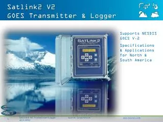
Satlink2. Satlink 2 Training Course. GOES HDR Transmitter. Satlink2 as a Stand Alone DCP Satlink2 and 8210 Satlink2 and 9210 Satlink2 and XPERT. Satlink2 as a Logger/Transmitter.

E N D
Satlink2 Satlink 2 Training Course
GOES HDR Transmitter • Satlink2 as a Stand Alone DCP • Satlink2 and 8210 • Satlink2 and 9210 • Satlink2 and XPERT
Satlink2 as a Logger/Transmitter • The majority of this training course involves setting up the Satlink as a stand alone DCP because when the Satlink is used with one of the other data loggers the other data logger controls measurements and transmissions schedules.
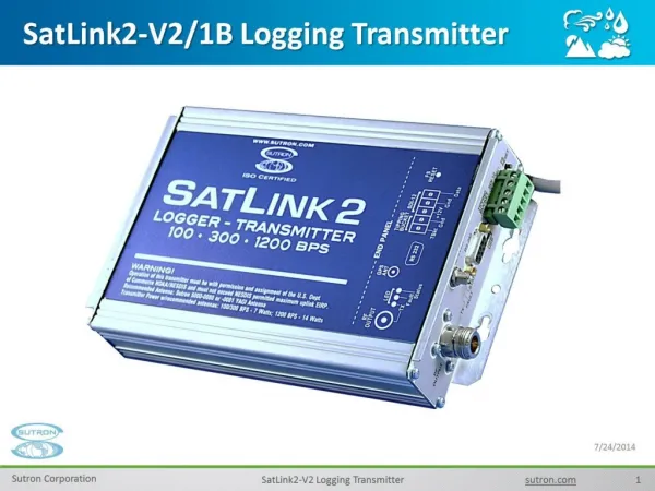
SATLINK2 GOES SATELLITE TRANSMITTER/LOGGER 16 INDEPENDENT MEASUREMENTS 4 ANALOG INPUTS, SDI-12, RAINFALL TIPPING BUCKET INPUT BUILT-IN LOGGER POCKET PC, LAPTOP PC, DESKTOP PC COMMUNICATIONS VERY EASY SET-UP & OPERATION VOICE AND DATA MODEM OPTION PROCESSES NON-LINEAR SENSORS SD CARD SLOT MIN/MAX PROCESSING EASILY INTEGRATES WITH EXISTING OR NEW SENSORS, STATIONS & LOGGERS TRIMBLE GPS FOR FAST SATELLITE ACQUISITION POWERFUL MATHMATICAL EQUATION EDITOR
Manual and Software • Manual and Satlink Communicator SW Provided on CD • Fully Programmable Via The Front Panel Keypad • Manuals, Upgrades and Interface SW Available at www.sutron.com • GPS Antenna • PDA – Satlink2 Operation • Satlink2–Bluetooth Wireless Communication
Specifications • Specifications • Weight: 2.2 lbs. • Size: 5.55 in. x 7.70 in. x 1.75 in. • Environmental: -40°C to +60°C • Operating Voltage: 10.4 to 15 VDC, reverse voltage protected • LED Indicators • Status • Fault • Transmit • Connections • Power: Built-in cable • GPS: SMA (Bulkhead Mounted) • RS-232: DB9 • SDI-12: 3 position removable terminal strip • Tipping Bucket: 2 position removable terminal strip • 4 - Analog inputs: 8 position removable terminal strip • RF: N-Type • Supports other DCPs in dumb logger mode at 9600 baud
Specs Continued • Recommended Antenna • Sutron YAGI (10.5 dB gain), 5000-0080 • Transmission Modes • 100 BPS random and scheduled • 300 BPS random and scheduled • 1200 BPS scheduled • 4800 BPS INSAT selectable 10 min. window (3 randomized repeat sequence) • METEOSAT Alert & Self Timed • ARGOS/SCD Format • Transmission Character Sets • ASCII • Pseudo binary • Transmitter Output Power • Software selectable power levels • 7 Watt nominal, 100/300 BPS (+/- 1dB) • 14 Watt nominal 1200 BPS (+/- 1 dB) • 3.5 watt (adjustable to 18 watt) INSAT
Specs Continued • Log • 120,000 floating point readings • Individual time stamps to 1 second • Can log numbers as small as 1E-38 or as large as 3E+38 (IEEE32 float) • Non-volatile flash memory • Quality flag for each value • Data • Data Merge Mode supports merging of Satlink Logger data with data from external logger prior to transmission • Circular Buffer Mode - enhanced transmission data management. Excess data is stored & sent on subsequent transmissions. • Alarms • User configurable for each sensor • Alarm types: high alarms, low alarms, and rate of change alarms • Timekeeping • Sync to GPS • within 10 ms UTC • Frequency discipline to within 10Hz • Power Requirements @ 12.5 VDC • Quiescent: 6 mA typ • 300 BPS Transmission: 3.8 A (Typ) • 1200 BPS Transmission: 4.8 A (Typ) • Protection against open or short circuit loads on transmitter output
Common Optional Items • M-F DB9 cable • M-M Null Modem Gender Changer (Sutron part number 3121-1700) (used with IPAQ Pocket PC) • Sutron YAGI antenna • Sutron 15-foot RG-8 antenna cable • Lightning arrestor for RF output cable • Extension cable for GPS antenna • Solar panel w/ regulator • Battery • Grounding cable kits
DC INPUT POWER • DC input power is not critical to the transmitter as long as it remains in the range of 10.4 to 15 volts DC. The transmit power is independent of this voltage in this range thereby eliminating varying amount of watts with low battery conditions. It is important to have a well charged battery that is capable of delivering 5 amps without significant sagging under the load during the transmission. The transmission will abort if the voltage drops below the 10.4 volts, the range in which the battery is considered failed. The Satlink 2 will continue running without transmitting well down to the 7 or lower volt range.
Satlink Front Panel Lights • There are three LEDs on the front panel of Satlink. When power is applied to Satlink, all three lights will come on in sequence, indicating that Satlink has booted. Afterwards, one of the following scenarios will occur: • Green light blinks once every five seconds – this is the desired state. It means Satlink is up and running, making measurements and transmissions depending on the setup. • Yellow LED blinks every 10 seconds – Satlink has not been setup. It is stopped and will not make transmissions or measurements. To correct this, connect to Satlink via the Communicator program, set it up, and hit Start. • Yellow and green LEDs blink every 5 seconds – Satlink is running but is having GPS trouble. If the yellow light does no go away after two or three minutes, recheck the GPS antenna and make sure it is properly connected and that it has good view of the sky.
Front Panel LEDs • Yellow LED blinks every 5 seconds. – Satlink is stopped, and the GPS does not have satellite lock • Yellow light blinks twice in a row every two seconds – this is bad. Satlink thinks it is malfunctioning. Either it has bad hardware, is unable to transmit or some other failure. Connect to Satlink with the Communicator program, and the details of the failure will be revealed. Once the problem is fixed, the blink should go away. • Red LED is on solid – Satlink is transmitting (there is power being output through the RF connector). • Green light is on solid – Satlink is getting ready to transmit. You should see the red light come on soon. • Green light blinks twice – Satlink is making a measurement. • Green and yellow LEDs are blinking madly – Satlink’s software is being upgraded.
Working Disconnected • Working Disconnected from Satlink allows you to create or modify a complete setup in your office and then transfer the new setup to the Satlink on the next site visit • This also works as a training tool to help you understand Satlink setups
Quick Status Icons • The indicates a good state. • The“X”indicates a bad state. • The“?”indicates a “maybe” state which may either be intended by the user, or it may be that Satlink was not setup properly.
Configuring Satlink 2 • Set the system to defaults. If this is a new unit, it should already be in this state. If not, the user can set the system to factory defaults using the Communicator program (Diagnostic tab of the Communicator program). • Set up Satlink’s configuration: This involves setting the measurement types and schedules, as well as transmission interval, times, and satellite ID. The details of setup are described in the Manual chapter titled “Using Satlink Logger Communicator”. • Each part of the setup should be tested. If sensors are connected, measurements should be tested by forcing a measurement and by examining the results. A transmission can also be forced. Make sure to transmit into a dummy load – not on air. Monitor Satlink’s status to ensure that it reports a successful transmission. • Start Satlink, just to ensure that the setup is proper. If the setup is invalid or incomplete, Satlink will notify you of the problem. Otherwise, it will go into running mode.
Graphing the recent measurements is accomplished by hitting the graph button which appears on the Quick View status, on the data tab, and in the Tools menu. • Graphing logged data can be invoked from the log download window which appears when the user hits export log from the data tab, and from the tools menu. The user is also given the option of graphing previously downloaded log files that are on his disk.
Show Message (not available on Satcomm)
Test Tx The Test Tx functions should only be performed by someone trained in the operation of the transmitter. They should never be done with an antenna connected as the tests can disrupt the transmissions from other stations. Warning: Never perform tests with the antenna connected as violation of transmission assignments may occur.
NOAA NESDIS • In order to properly use Satlink Logger, you must first be familiar with the Satellite system on which Satlink Logger operates. If you are planning to operate your Satlink Logger in North or South America, you will be using the GOES satellites operated by NESDIS. Currently there are two satellites in geostationary orbit in the NESDIS DCS system. In order to make transmissions on the satellites, you will need to contact NESDIS and fill out their required applications. The main web site for NESDIS DCS is http://noaasis.noaa.gov/DCS/. After completing the applications you will be assigned an ID, transmission time, interval and channel. • NESDIS requires that you keep the PDT file up to date for any station operating in the system. Whenever you deploy a station or move it, you should make the appropriate changes in the PDT file.
More About GPS Antenna • Place the GPS antenna in the most open space possible. Do not place it directly under anything nor directly beside something. Always attempt to achieve a "full sky" view with the antenna. • Place the GPS antenna high up on a pedestal or in a protected location. Flat surfaces may tend to cover with ice and snow more so than elevated locations.
Even More About The GPS • Keep away from areas where birds may nest. Placement is very important and great care should be taken in selecting the location.
GPS Time Sync • In recent timing tests conducted by the US National Ocean Service (NOS) a SatLink2 connected to a tide station made over 350,000 transmissions without deviating a single second from the assigned time window