Download
1 / 51
550 likes | 1.12k Views
Dimensioning & Projections. Dimensions. Dimensions are used to describe the sizes and relationships between features in your drawing. Dimensions are used to manufacture parts and to inspect the resulting parts to determine if they are acceptable.

E N D
Dimensions • Dimensions are used to describe the sizes and relationships between features in your drawing. • Dimensions are used to manufacture parts and to inspect the resulting parts to determine if they are acceptable. • Drawings with dimensions and notes often serve as construction documents and legal contracts. • ANSI Y14.5M-1994 is the current standard. Other standards may apply.
Standards for Your Career Field • Standards are different in different career areas. • Most of the examples in this lecture will be of mechanical parts. • Civil, Electrical, Construction, and other areas follow similar practices, but sometimes with less need for precision in measurements. • Dimensioned drawings are a part of a contractual document.
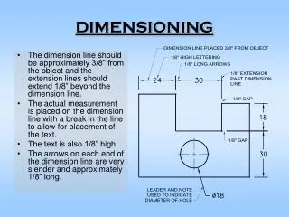
Vocabulary Dimension line, Extension line, Leader, Dimension offset or gap, Centerline, Finish mark, Dimension value Baseline dimensioning, Chained dimensioning
Tolerance Definition: The total allowable variation an acceptable part can have from the specified dimension. The less variation allowed, the more the part will cost to make.
3 Things for Good Dimensioning • Good technique of dimensioning • Good choice of dimensions • Good placement of dimensions
Dimensioning Technique • describes how the dimensions in your drawing should look. • defined by various standards like ANSI Y14.5-1994. • help you create dimensions that are plainly visible and can be easily interpreted. • specifies sizes for creating dimensions relative to the paper size of your final plot.
arrowheads extension lines dimension lines sizes use thin, dark, lines (HB lead) make object stand out clearly! Dimensioning Technique
Orientation forDimension Values • Unidirectional: • read horizontally from bottom of sheet • Aligned: • align with dimension line and read from bottom or right side of sheet
Choice of Dimensions • the dimensions you specify determine the way the the part is manufactured and the way the tolerance is applied • consider the purpose of the part and its function in the assembly • consider how easy it will be to check the measurement on the actual part • fully dimension each part • do not overdimension, each dimensions should appear only once
Don’t over dimension Give the diameter of circular shapes, the radius of arcs. No redundant or superfluous dimensions Give size dimensions for features. Give location dimensions to show how features relate to one another. Choosing Which Dimensions to Show
Baseline each dimension is specified from a common baseline tolerances do not stack Chained each dimension continues from the previous one tolerances stack Effect of Tolerance on Dimensioning
Units • Fractional Inch • Decimal inch dimensions are typically specified to 2 decimal places. • Metric values are typically given in whole millimeters or to one decimal place.
Placement of Dimensions • Rules-of-thumb for dimension placement help ensure that others will be able to interpret your drawing • Where placement practices conflict, remember that your goal is to clearly communicate the purpose of the drawing. Use the practice you feel will make the drawing easy to understand.
Avoid dimensioning on object (face of part). Avoid dimensioning to hidden lines. Place dimensions between views when possible. Don’t “float” dimensions. Place dimensions where feature shows shape. Give overall dimensions where possible. Group dimensions around a central view. Placement Practices
Summary • Good dimensioning is a combination of choosing dimensions which reflect your design intent, proper technique in creating the details of the dimension line, extension line, arrowheads and dimension values, and placing the dimensions on the drawing so that they can be read clearly. • Dimensioning drawings correctly can be as important or more important than drawing the shapes correctly. • Good dimensioning requires practice and thought!
Orthographic Projection a system of drawing views of an object using perpendicular projectors from the object to a plane of projection
The Glass Box • Imagine that the object you are going to draw is positioned inside a glass box, so that the large flat surfaces of the object are parallel to the walls of the box. • From each pointon the object, imagine a ray, or projector perpendicular to the wall of the box forming the view of the object on that wall or projection plane.
Unfolding the Glass box • For Third Angle Projection (the method in the U.S.) • Imagine that the walls of the box are hinged and unfold the views outward around the front view. • This will give you the standard arrangement of views for 3rd Angle Projection which is used in the US, Canada, and some other countries.
The Standard Arrangement of Views TOP LEFT FRONT RIGHT BOTTOM REAR Why must views be arranged so that they align? To make it possible for someone to interpret the drawing.
Using a Miter Line to Transfer Depth 1. Draw miter line at 45 degrees at a convenient distance to produce the desired view.
Sketch light lines projecting depth locations for points to miter line and then down into side view as shown. 2.
4. Draw the view locating each vertex of the surface on the projection and miter line.
Necessary Views A sketch or drawing should only contain the views needed to clearly and completely describe the object. Choose the views that show the shape most clearly, have the fewest hidden lines, and show the object in a usual, stable, or operating position. One view drawing of a shim One view drawing of a connecting rod
Position of Side Views An alternative postion for the side view is rotated and aligned with the top view.
Symbols for 1st & 3rd Angle Projection Third angle projection is used in the U.S., and Canada