Download
1 / 17
170 likes | 178 Views
This article discusses the considerations for module vacuum systems, including the appropriate pressure, gas loads, pump selection, sectorization, vacuum monitoring, and miscellaneous design elements.

E N D
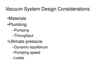
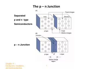
Considerations on the module vacuumP. Costa Pinto N. Hilleret Summary Specifications: P Key points: Gasloads A scheme for the vacuum system Considerations on Module vacuum systems
What Pressure?? See D. Schulte talk: Fast ion instabilities Drive beam: 1nTorr Main beam: still uncertain Considerations on Module vacuum systems
What Pressure?? • Production of ions (neutralisation)? Considerations on Module vacuum systems
What Pressure?? • Users requirements: RF: • No influence of bake out on conditioning • Model developed for breakdown in agreement with experimental results: no vacuum depending parameters • Tradition?=> 10-6 Pa • Doubts with “Fast Ion Instabilities” 10-8 Pa? Considerations on Module vacuum systems
BAKED GAS LOAD • Unbaked system=> Water predominates • S~10 m2/module MB ,S=50 l/s Considerations on Module vacuum systems
GAS LOAD • Baked • Expensive • Mechanical constraints (thermal elongation) • Extra space needed for bellows • Space in quadrupoles? • Lower pressure in shorter time • Unbaked • More demanding in terms of materials/cleanliness (ferrite excluded) • Longer time to achieve “good” pressure • Reduced thermal elongation=> less constraints on bellows=> more space • Cheaper operation • Less constraints on Quad aperture Considerations on Module vacuum systems
Gas Load • Dynamic: e- induced desorption? • 10J/breakdown (Walter) Considerations on Module vacuum systems
Gas Load • Dynamic: e- induced desorption? 10J/breakdown (Walter). Electron Energy: 100 keV: stopping force reduced by~10 (compared to 300 eV) • => Breakdown liberate ~ 1015 mol/breakdown ( 4x10⁻⁶ Pa.m3) Considerations on Module vacuum systems
Spark in cell 70 Gas Load • Dynamic: irrelevant for vacuum design • Cell Pressure entirely determined by structure design Simulation for HDS (30GHz) For 11GHz structures conductance per cell is ~30x higher Per structure ~4x higher 30GHz 11GHz S[l/s] S/l/s] increase H2/cell 0.02 0.56 28.9 CO/cell 0.01 0.15 27.5 H2/struct 10.934 45.15877 4.1 CO/struct 3.035658 11.90549 3.9 Considerations on Module vacuum systems
Gas Load • Dynamic: irrelevant for vacuum design (If no influence of bake out) • Gas load during breakdown : pretreatments • Pumping speed independent of pumps (conductance) • Breakdowns transients pumped by container volume: VdP/dt Considerations on Module vacuum systems
PUMPS • MAIN PUMPS: • Pumping during breakdown: • holes in the structure • P recovery between breakdowns: • Volume of the vacuum tank • Mean pressure • External pumps • Example:Breakdown dP/dt=10-6Pa/ms, P=10-6 Pa • Q pump: P=10-6 Pa, 1000l/s=>Q=10-3Pa.l/s • Q vol (200l) =>Q= 2 10-1 Pa.l/s Considerations on Module vacuum systems
PUMPS • Preevacuation: Mobile TM stations (access??) • Holding pumps: Ion+ Capture pumps • Ion: 50 l/s => • Pump ignition ~ 1day • start up of structure operation (1 week) • Su pumps for hard conditioning/ operation (~1000 l/s) • Cheap reliable • Efficient after ~ 2 weeks • Tests needed (speed/capacity for water?) • Alternate: Cryogenic pumps/TM pumps • Expensive (very) • Reliability ? (expensive maintenance) Considerations on Module vacuum systems
Sectorisation • Each quadrupole is a barrier (0.4 l/s conductance) • Length of sector determined by: • Money (1 valve~ 20kCHF) • Space lost (~ 10 cm minimum) • Operation: in case of failure or modification all the length vented=> reconditioning. Failure rate? • Guess : • 1% total length (20km=>200m) • lost space (≥100 mm) • 100 sectors=> 10m • 200m long sectors: 1% of the accelerator opened (i.e. reconditionned) per failure Considerations on Module vacuum systems
Vacuum monitoring • One valve (manual) on vacuum envelope per girder • Ion pump used for vacuum measurement (reliable above 10-6 Pa)=> provides VAC interlocks • When problems: magic box connected to the valve: (gauge, RGA…) • Leak check made per girder (lengthy) • Possibly by-pass between two tanks Considerations on Module vacuum systems
Miscellaneous • Construction element: 1 girder (~2m) • In case of problem transported as a block to the lab • Avoid any unnecessary constraints : • Cheap (hopefully) welded vacuum tank • Geometry ±some mm • Tank cover with bellows at the beam pipe (no load on the fragile beam tube) • Welded beam tube junction (no flange but space for automatic welding machine) • Possibility to bake each girder before installation? Considerations on Module vacuum systems
Possible quad chamber design • Produced in 2 halves • Machined (accurate parts) • Longitudinal weld between 2 profiles • NEG strips in the appendixes (Pumping and heating elements) • To be adapted to actual quad design • Integrated pump~ 10l/s/m • To be checked for feasibility, cost and performance Considerations on Module vacuum systems
CONCLUSIONS • Most important question: design pressure? • =>Choice between baked/unbaked system • Achievable pressure in cells determined only by geometric constraints • Connexion between module/BPM/quadrupoles must be studied: space, technique… Considerations on Module vacuum systems